A capacitive level sensor (CLS) is a contact free way to measure the level of any fluid or powder. It measure the height through the change in Relative permittivity that occurs when water replaces the air in the sensor. The sensor uses an Atmega328 to measure the capacitance and sends this value to a main controller through I2C. The sensor can be made without any complicated tools and using only off the shelf parts. It has a measuring accuracy of around 0.25% to 1% of the length and is completely waterproof.
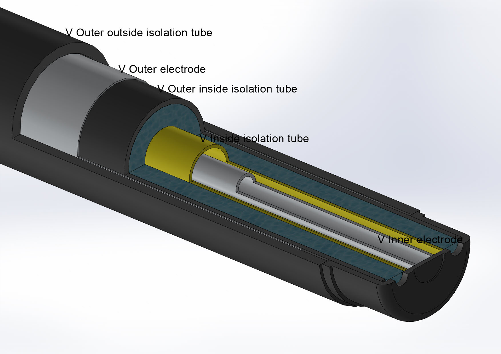
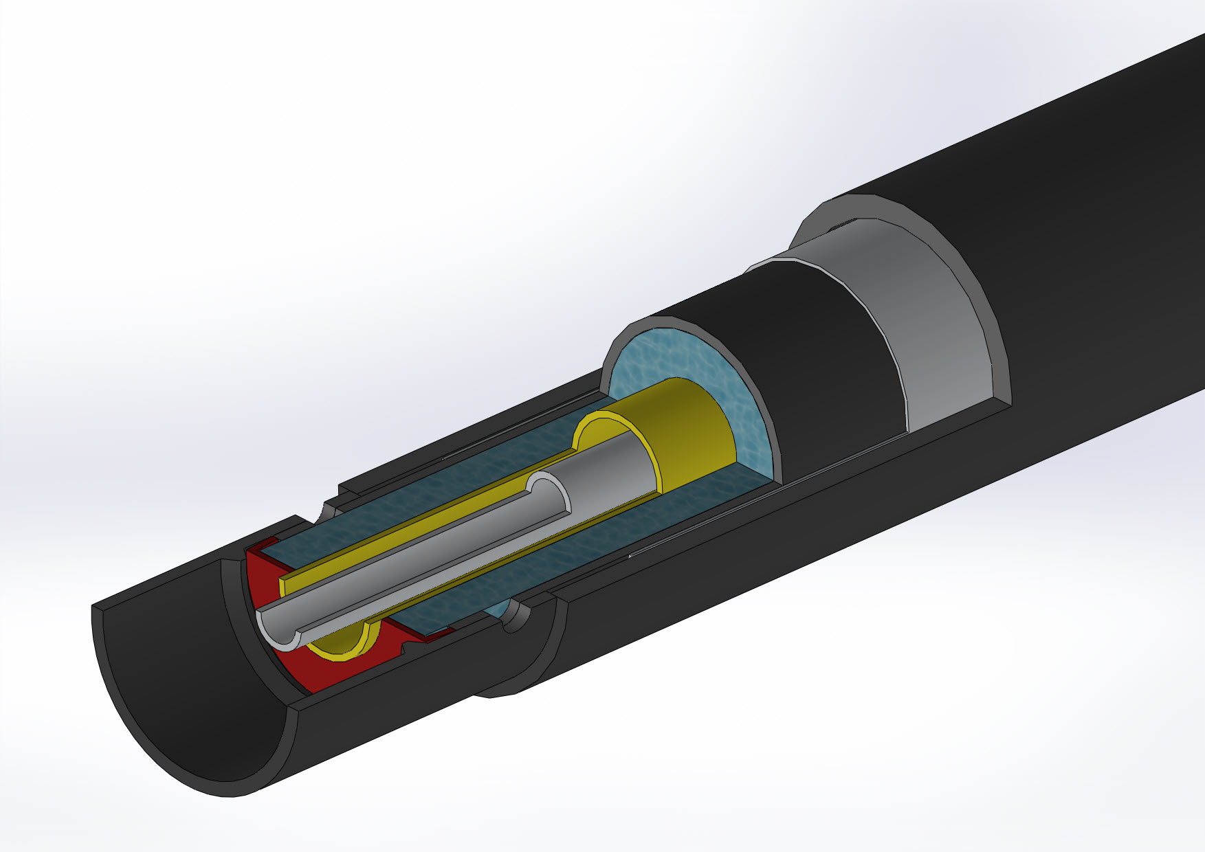
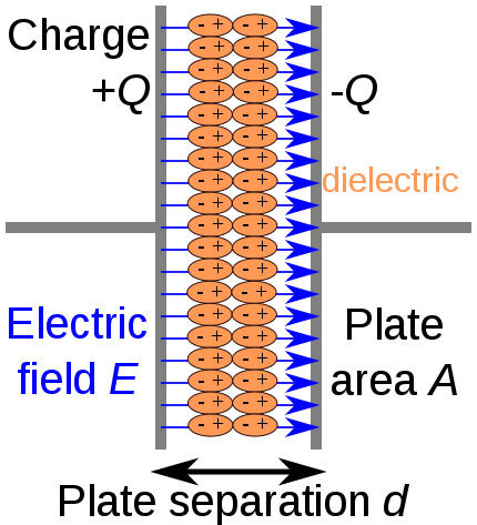
To understand how this sensor works, you will need to understand a capacitor: http://en.wikipedia.org/wiki/Capacitor. Basically a capacitor is two conductive plates, separated by an insulator (dielectric). When a charge is applied to these plates, the dielectric is electrostatically charged. With the sensor the two plates are replaced with two concentric tubes, one larger than the other. The two tubes are electrically isolated and have an air gap between them. This whole set of tubes is suspended in the vessel where the level needs to be measured. When the level rises, the tube fills and the air is replaced with the medium being measured. This medium has a different relative permittivity than the air and so the capacitance of the sensor changes. This capacitance is measured by the on board microcontroller by charging the sensor and measuring how long it takes. The higher the capacitance, the longer it will take to charge the sensor and the more of the medium will be in the sensor.
The advantage of capacitive level sensor is that they can measure any fluid or powder without ever making contact with it. This means the sensor can be made food-safe or resistant against corrosion. Also the sensor can be made in any length without any problem, the sensing part of the sensor scales incredibly easy. The drawback of capacitive level sensors is that they need to be calibrated for the substance being measured. When they need to measure a different substance, they need to be recalibrated. CLS also become weak when the measuring range becomes above several meters.
Making a Capacitive Level Sensor
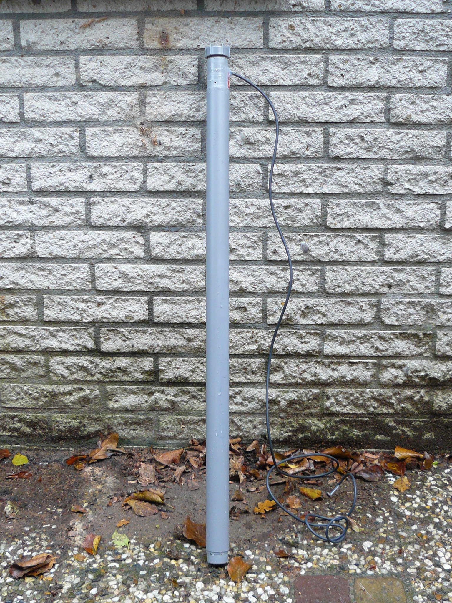
The sensor is made from easily obtainable materials. The main body is made of PVC tubing and the plates are either aluminium tube, or aluminium tape wrapped around a tube. The sensor is sealed with silicone caulk, so it is pond and aquarium safe (but probably not really food safe). Exact measurements are not really that important, it is more important that relative sizes are correct. Also this sensor is made with Dutch PVC pipes and fittings. If you live anywhere else, you will have to use your imagination. To make the sensor you will need following materials and tools:
- 40mm x 3.2mm PVC tube
- 32mm x 1.6mm PP tube (fits with a 1mm gap into the 40mm pvc)
- 5/8″ electrical PVC tube (fits around the aluminium tube)
- 8x1mm aluminium tube
- 32mm PVC endcap
- 32mm PVC coupling
- 32mm PVC screwcap
- 32mm plug
- electrical tape
- Aluminium tape
- Silicone caulk
- Wire
- 4 pole wire
- Tie rips
- A straw
- 1 barebones Arduino uno (or any other mini arduino)
- 3 18Mohm resistors (or comparable high resistance resistors)
- Another Arduino to check and calibrate the sensor (and an Uno to program the barebone)
- 2 4k7ohm resistors for the I2C
- A caulk gun
- A cordless drill
- A hacksaw
- Files
- Pliers
- Wire cutters
- Soldering equipment
First you will need to cut the tubes to length. The longest tube is the small aluminium tube. The small PVC tube needs to be 1-2cm shorter than the small aluminium tube. The 32mm PP tube needs to be 1 cm shorter than the small PVC tube, and the 40mm PVC tube needs to be 4-5cm shorter than the 32mm tube (so that when the end cap and coupler are mounted, the 32mm tube is not visible. A small notch may have to be cut in the inside of the 40mm PVC tube to make the wire fit past the coupler.


The outer plate (electrode) is made by wrapping aluminium tape around the 32mm pp tube. Spiral the tape around the tube and stick a stripped wire underneath the tape. This wire will connect the controller to the outer electrode. Then with a knife cut the edges of the outer tube in such a way that the tape is removed to 1 cm above the endcap and coupler. Don’t cut through the wire when cutting the tape.
The inner electrode is made from the small PVC tube and the aluminium tube. Tape a stripped wire to one end of the aluminium tube and use something like electrical tape to create a spacer for the small aluminium tube on both sides. The aluminium tube needs to be neatly centred in the small PVC tube. Slide the aluminium tube in the small PVC pipe.
Cut the 32mm plug in such a way that the small PVC tube fits through it and that the plug fits in the coupler. This will be the barrier that stops the water from entering the electronics compartment.
To assemble the sensor, first deposit a generous dot of silicone in the endcap, then place the bottom of the inner electrode (the side with no wire) in the endcap, making sure it is in the center. Then apply a small amount of silicone outside the bottom of the outer electrode and push it in the endcap. Apply a generous amount of silicone caulk around the bottom of the outer electrode and twist the large 40mm tube around the outer electrode. Make sure the 40mm tube has a good seal with the endcap. Then apply silicone around the top of the outer electrode and place the coupler with the plug over the whole assembly. Make sure the small inner PVC pipe doesn’t move in the bottom when the plug goes around the small PVC tube. Then seal the entire plug, small PVC tube and aluminium tube from the top with silicone. Use water with dishwash liquid to smooth out all of the seals. Let the tube assembly dry for a few hours.
Use a drill bit the size of the straws to cut holes in the endcap and coupler (both on the wet side of the sensor). It is absolutely vital here that the small PVC tube or the wrapping of the outer electrode are not pierced. The water should never be able to touch these parts. Straws can be used in the bottom holes to prevent the silicone from collapsing if it is still wet. The use a small drill to cut a hole for the wire of the outer electrode to enter the electronics compartment and then use a drill the size of your 4 pole wire to cut a hole for the 4 pole wire. Push the 4 pole wire through the hole, secure it with a tie rip on the inside, pull it to the tie rip and use another tie rip on the outside. Then seal the outer electrode wire and 4 pole wire with silicone caulk.


When the entire sensor is dry, it can be tested. I used an LC meter to measure the capacitance when dry and full, to see if there is a difference. This step can be skipped, but it does provide a lot of insight in the sensor. The barebone Arduino was soldered dead bug style. The following steps were followed to make the controller. The controller can be programmed before it is being soldered, but I soldered a programming header to it, so I waited with programming until the sensor was in the tube.
- Solder 3 18Mohm resistors in series to make 1 54Mohm resistor;
- Use tape to isolate the 54Mohm resistor;
- Solder the crystal to the Xtal pins of the arduino;
- Solder the 2 capacitors to the ground next to the Xtal pins;
- Solder the 10k resistor from the 5V to the reset;
- Solder all 5V lines together;
- Solder the 2 ground pins together;
- Solder wires to the I2C lines (SDA and SCL, A4 and A5);
- Solder I2C power wires to the 5V and ground;
- Solder a programming connector to the 5V, ground, reset, Rx and Tx;
- Solder the 54Mohm resistor in between the measurement pins;
- Solder a wire to one of the measurement pins and solder another wire to the ground (capacitor wires);
- Tin the wires coming from the tube;
- Solder the I2C and sensor measurement wires to the barebone Arduino;
- When all is tested, stuff the Arduino in the tube and test again.
It is important here that the outer electrode is connected to the ground and the inner electrode is connected to the controller. The other way around provides very little feedback.
Before you can upload the firmware, you will need to download and install the CapacitanceSensor library. It can be downloaded here and is installed like any other Arduino library. When the library is installed, open the code and compile it. To program the Arduino in the sensor, use this guide. Download the files for this sensor below. In the files there are 2 pieces of firmware. the first is called “CLS_sensor_firmware” This is the firmware for the sensor that measures the capacitance, recalculates it to a usable value and communicates this value through I2C. The other piece of firmware is called “CLS_sensor_reader”. This firmware can be uploaded to an Arduino that is hooked up to the sensor with 2 4k7 pull-up resistors. The reader can be controlled through the serial terminal of Arduino and is capable of controlling and reading the sensor.


The sensor communicates with I2C to the controller. I2C is a 2-way protocol that gives great control. It is not ideal for use through a cable, but it works fine for this application. The default address for the sensor is 42, but it can be changed in the firmware (though not through the I2C). There is 9 basic commands to request values and calibrate the sensor. A piece of example code is also included.
- 10: send 0-255 level value (returns 1 byte);
- 20: send distance in mm (returns 2 bytes, first the high byte, then the low byte);
- 30: send raw measure time (returns 2 bytes, first the high byte, then the low byte);
- 40: set sensor 0% value (nothing additional happens);
- 50: set sensor 100% value (nothing additional happens);
- 60: set sensor length in the unit you want (2 additional bytes are expected to be sent that specify the length of the sensor your chosen unit)
- 70: read the set lower limit raw value (returns 2 bytes (high byte first) with the set lower raw value);
- 80: read the set upper limit raw value (returns 2 bytes (high byte first) with the set upper raw value);
- 90: read the set sensor length (returns 2 bytes (high byte first) with the set length in the unit you picked)
//master request example
Wire.beginTransmission(42); //open communication
Wire.write(30); //tell the sensor what to do (30 = send raw value)
//additional writes can happen in case of 60.
Wire.endTransmission(); //end the transmission
Wire.requestFrom(42,2); //request 2 bytes from the sensor
if(Wire.available())    // if two bytes were received
{
  readValue[0] = Wire.read(); //read the first byte
  readValue[1] = Wire.read(); //read the second byte
}
Using it
Before the sensor can be used, it needs to be calibrated. The easiest way to do is is by hooking up the sensor’s I2C to another Arduino and using the CLS_sensor_reader firmware to set the values. The reader has a few (case sensitive) serial commands to control the sensor:
- ‘L’: set sensor lower value;
- ‘H’: set sensor upper value;
- ‘S’: set sensor tube length (value specified in firmware);
- ‘l’: read set sensor lower value;
- ‘h’: read set sensor upper value;
- ‘m’: read set sensor tube length;
- ‘R’: read current sensor raw value (is in ms);
- ‘P’: read the sensor 0-255 value;
- ‘M’: read the sensor level value (in the units you specified);
The first thing that is necessary is to set the sensor length. This is so that the sensor is capable of returning a length. To do this, measure the sensor’s length and modify the value in the code of the reader to this length.
word setValueMM = 800;
Then use the serial command ‘S’ to set the sensor length to this value. The command ‘m’ can be used to check the sensor length at any time. Additionally you can add this snippet of code to your own code to set the length of the sensor tube:
word setValueMM = 800;
byte tempSendValue[3] = {60, highByte(setValueMM), lowByte(setValueMM)};
Wire.beginTransmission(42);
Wire.write(tempSendValue, 3);
Wire.endTransmission();
Then you will need to calibrate the upper and lower points of the sensor. First place the sensor in the amount of medium you want to be registered as 0. Then use the ‘L’ command to set this point. You can read the lower set point with the ‘l’ command, which returns the raw sensor value for the low point. Repeat this step for the upper point. Submerge the sensor to the point you want to be registered as full, or ‘setValueMM’ and use the ‘H’ command to set this as the upper point. this value can be read with the ‘h’ command.
The snippets of code for the lower and upper point are as follows:
//set lower point
Wire.beginTransmission(42);
Wire.write(40);
Wire.endTransmission();

//set upper point
Wire.beginTransmission(42);
Wire.write(50);
Wire.endTransmission()
The sensor is now calibrated and ready for use. The values can be requested with serial commands: ‘R’, ‘P’ and ‘M’ or with the corresponding I2C commands found in the reader firmware. Mount the sensor in the location where you want to use it and measure that fluid without ever touching it.
License

The project described on this page is licensed under the Creative commons – Attribution – ShareAlike license.
Hello
I would like to talk to the owner of the project