Okay. I'm sharing some minimal code to get started: https://github.com/gkyle/xaar128
Usual caveats. I'm not handling errors, but this code at least counts failed fires, which happen (quite a bit when your nozzles clog). I'm using no external components that aren't called out on the wiki, so you can refer to code for connections and see some details on the adapter I'm using there. It looks like others are using some big caps on the 35v lines? I also think I see some level shifters (is that 3v>5v for logic?) I'm curious how others are wiring.
Here's some source for the Operations Guide (took some hunting to find):
http://d1.amobbs.com/bbs_upload782111/f ... HXZTX0.pdf
Hacking the Xaar 128 printhead
-
dragonator

- Site Admin
- Posts: 597
- Joined: Fri Aug 14, 2015 4:48 pm
- Location: The Nethelands
- Contact:
Re: Hacking the Xaar 128 printhead
That document and code is an absolute goldmine. The manual alone describes the full operation.
I can't wait to see people make stuff with the head using your data. I know I want to design with it.
I can't wait to see people make stuff with the head using your data. I know I want to design with it.
Re: Hacking the Xaar 128 printhead
Are you using external Quartz oscillator on the SLK pin?Kyle wrote:Okay. I'm sharing some minimal code to get started: https://github.com/gkyle/xaar128
Usual caveats. I'm not handling errors, but this code at least counts failed fires, which happen (quite a bit when your nozzles clog). I'm using no external components that aren't called out on the wiki, so you can refer to code for connections and see some details on the adapter I'm using there. It looks like others are using some big caps on the 35v lines? I also think I see some level shifters (is that 3v>5v for logic?) I'm curious how others are wiring.
Here's some source for the Operations Guide (took some hunting to find):
http://d1.amobbs.com/bbs_upload782111/f ... HXZTX0.pdf
EDIT:
Ignore this question. I see that you are not using external oscillator
Last edited by evomotors on Fri Sep 23, 2016 3:11 pm, edited 1 time in total.
Re: Hacking the Xaar 128 printhead
About the adapter:
You can find this one on eBay and other online sources to convert the Xaar 128 header to 16p IDS cable.

You can find this one on eBay and other online sources to convert the Xaar 128 header to 16p IDS cable.
Re: Hacking the Xaar 128 printhead
If someone is using one of these 16pin IDC-style connectors, it'd be great if they could document it on the wiki. I picked up a different one than you have pictured and I *think* it was for the Xaar 126 -- When I started mapping the pins, I found that some of the Test pins from the printhead were exposed from my Xaar 128 (so with only 16 pins, it would be missing critical I/O). If these IDC adapters work, they'll require less work for prototyping than the 21-pin adapter I'm using (which requires sourcing additional parts, but gives you an FFC cable you probably want long term).
Re: Hacking the Xaar 128 printhead
I ordered couple of connectors and will post the pin-out when I get them. But according to the website the connector is a Xaar 128 transfer board to connect it LIYU printer. It's bunch of websites selling them, the only issue is that all in China.
http://www.ebay.com.au/itm/NEW-LIYU-PM- ... 1893417464
http://www.ebay.com.au/itm/NEW-LIYU-PM- ... 1893417464
Re: Hacking the Xaar 128 printhead
Hello. Please, could you share the wiring diagram printhead xaar 128 to arduino. I would be very grateful.
Re: Hacking the Xaar 128 printhead
hello everybody, i´m Carlos from Brazil, i´m buying the xaar 128 and i will try to work together.
-
CCinCapital
- Posts: 1
- Joined: Wed Oct 05, 2016 12:43 pm
Re: Hacking the Xaar 128 printhead
Hi guys,
I bought a adapter for the XAAR 128 that has a 14pin FFC connector on it, this is the pin map:

And, the adapter looks as same as this one:
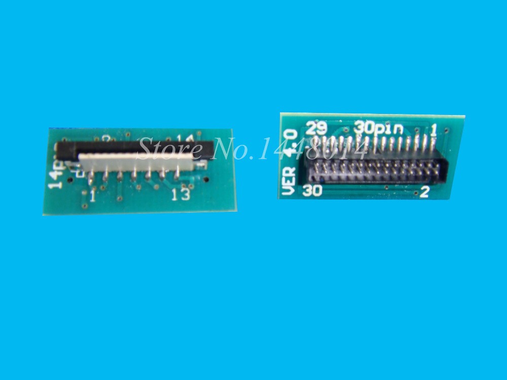
I bought a adapter for the XAAR 128 that has a 14pin FFC connector on it, this is the pin map:
And, the adapter looks as same as this one:
Re: Hacking the Xaar 128 printhead
@Kyle - Have you made any new progress? what kind of ink have you tried so far?
Also in your code that you posted on gihub you void printSummary(float fails, float steps). Is this outputs to display?
I'm not Arduino programmer so it's harder for me to understand because you are saying that you are not using any external components that aren't called out on the wiki, so I'm just asking to confirm...
Code: Select all
void printSummary(float fails, float steps) {
  Serial.println("Done.");
  float f = fails / steps;
  Serial.print("Steps: ");
  Serial.print(steps);
  Serial.print("    Fails: ");
  Serial.print(fails);
  Serial.print("    Failure Rate: ");
  Serial.println(f, 4);
}