Home › Forums › 3DP printing › Step 1, Hacking the CN642A inkjet printhead
- This topic has 75 replies, 6 voices, and was last updated 9 years ago by
yegorvd.
-
AuthorPosts
-
September 25, 2014 at 10:18 pm #1645
wonko
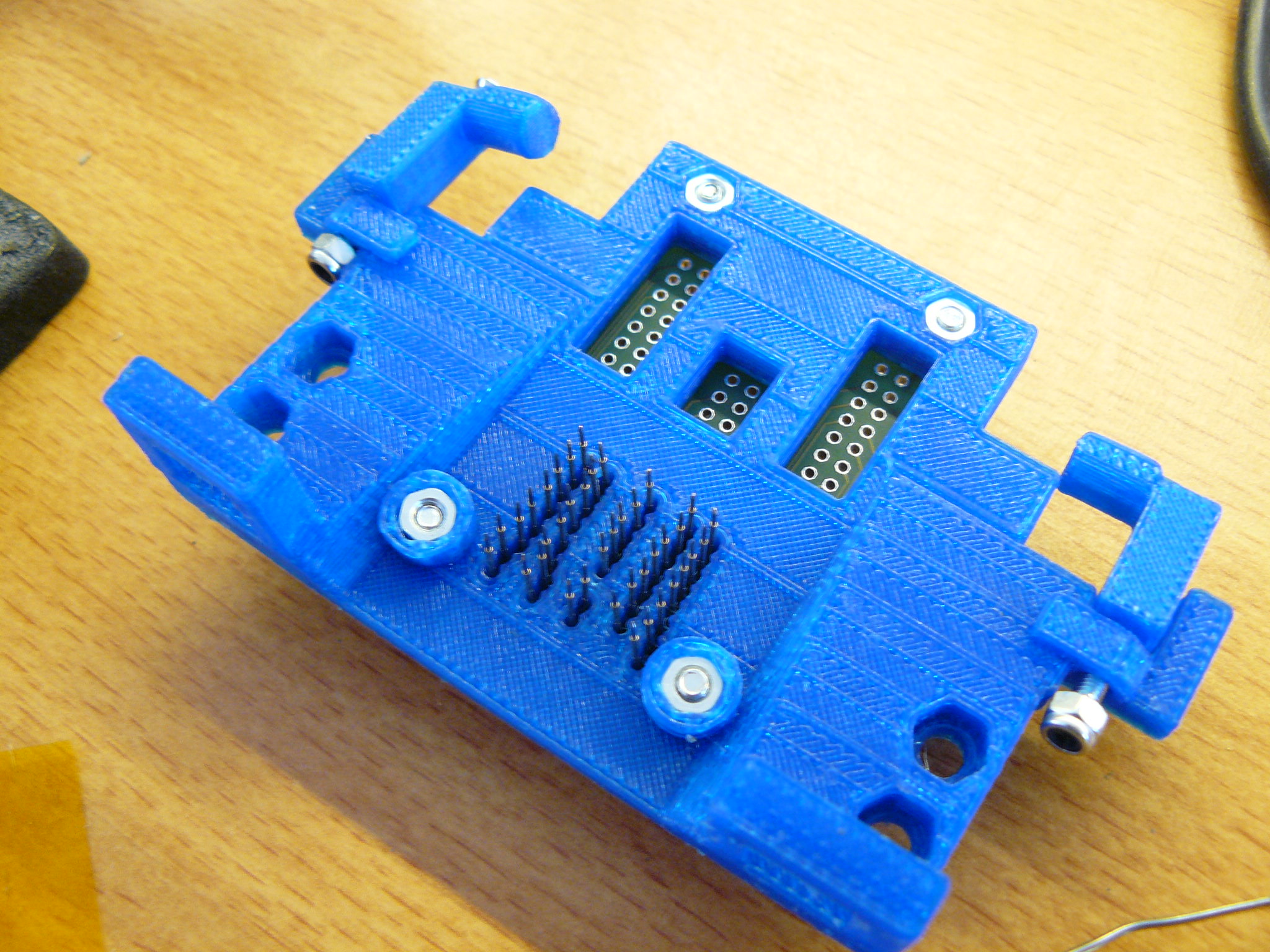
ParticipantHere is how to solder the pogo board. The name comes from the spring-loaded contact pins in the picture above that look like ant-size pogo sticks. They are needed to connect the foil contacts on the print head to the electronics in the printer. Commercial printers use another foil that has contacts with dents that are pressed against the printhead. But these foils are custom made and extremely expensive as one-offs, though cheap in the thousands.
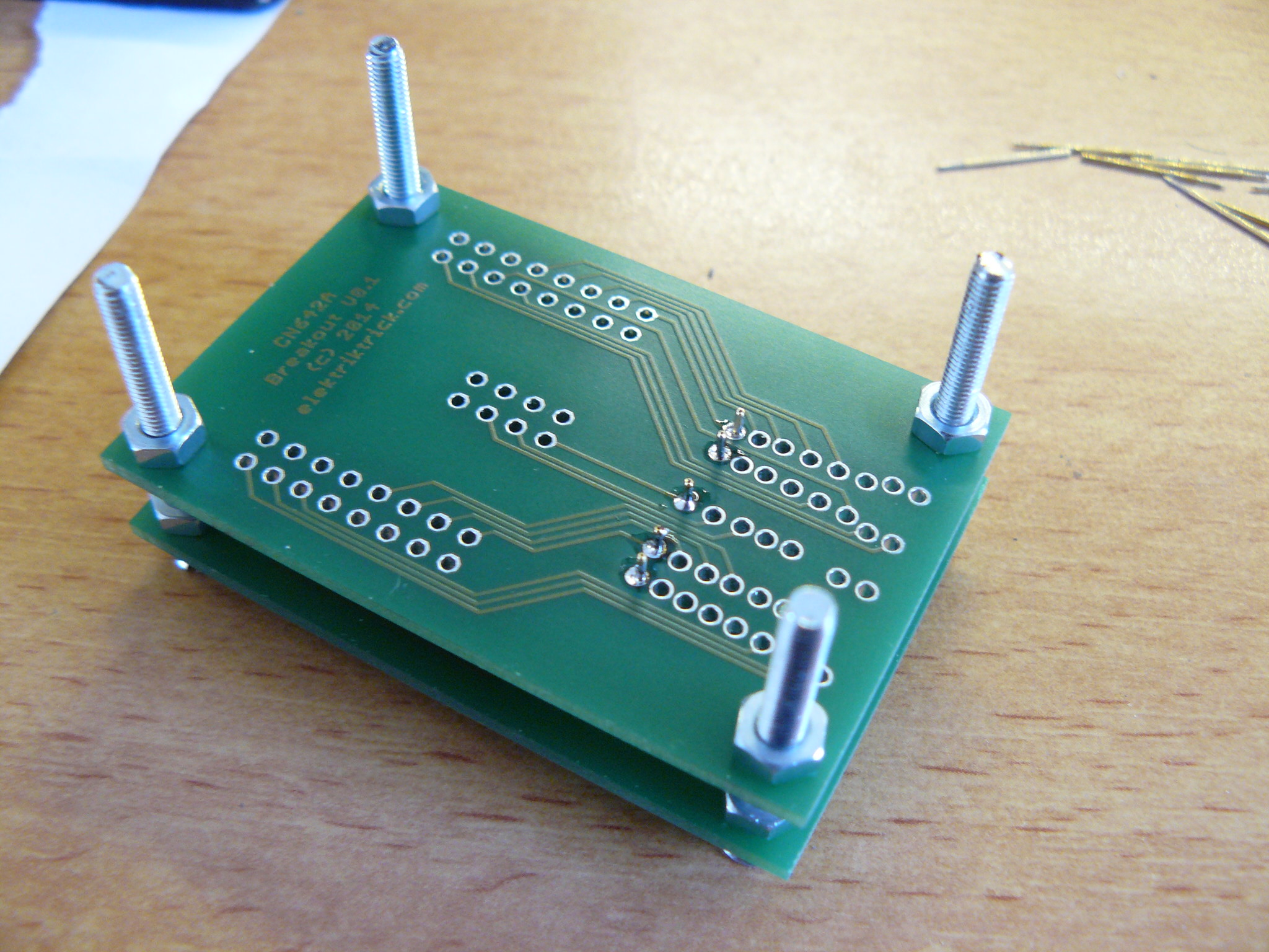
Our Pogo Board uses a PCB with holes just big enough for the pins, and 36 pins that must all be soldered in straight and with the same length.
We use two PCBs to form a rig for the depth, using four 3mm bolts to create the correct space. Feel the distance from the PCB to the foil by mounting everything in the holder and using a wire as a doth gauge. Mount the top board 2mm higher than the depth gauge to allow for some compression of the pogo pins. Lay flat and solder away!
Oh, you should test each pin before soldering it in to avoid desoldering duds. Also, make sure that the springy end points down before soldering.
September 25, 2014 at 10:20 pm #1646Participant


 September 25, 2014 at 10:26 pm #1647Participant
The first picture shows how the rig is built. The top PCB is the final carrier and takes the soldering. The lower PCB is there only as a guide, keeping the pins straight during the soldering process. The height of the top board is essential. It help to hold the rig down onto a flat surface while soldering…
The second image shows 15 pins soldered in, and a 16th pin waiting to be dropped all the way to the surface. Do not compress the spring while soldering!
The third image is the view from below with all pins soldered in. Remove the bottom template…
… and you will get this nicely alined straight and even length pogo pin board. Fit it into the holder and insert a print head. If the spring load is too high, add a washer to enlarge the distance to th printhead and reduce tension. One pogo pin is easy to compress, but 36 of them exert – um – 36 times the force.
Now, who’s going to solder in the wires and shoot the first droplet 😉 ?
September 27, 2014 at 11:09 am #1651dragonator
KeymasterFollowing the handy guide you provided, I too soldered one of your breakouts, which arrived last Friday. The guide was clear, but somehow, I managed to get the thinnest pogopins on this planet (0,7mm) which made the holes a wee bit too big (as in way too big). The pins had some freedom and did go a bit to the side, but I think the circuit will be fine. I have already had the printhead against it, and I think they make full contact.
I did consider your point about my pointy pogo pins puncturing the copper contacts, but when I tried, a single pogopin did not give me the idea that it was about to go through. It is indeed funny how 36 (-38?) pins push back with such a force. I have 45g per pin, something which I didn’t believe when buying, but do believe now. It takes way over a kilo of force to push them all in at once.

I don’t know yet who will be the first. I will probably do it next weekend, since these printhead can dry out and I want to do as much of the hacking in one smooth go. I will make my preparations this weekend and the coming week, so I can start testing at the start of the coming weekend and hopefully have some real progress by the end of that weekend.
September 27, 2014 at 7:19 pm #1653KeymasterToday I received the reason why I picked the CN642A as my starting choice. The CISS systems that are available for it. Completely empty and ready to be filled with whatever I want in it. While I will not hook up the CN642A to my arduino this weekend, I will design an addition to the carrier that allows me to properly mount the cartridges. Also the notches holding the carrier need some alteration, they don’t keep the carrier flush.
 September 30, 2014 at 7:34 pm #1659Keymaster
Disaster struck today. As I was preforming minor maintenance on my UP! plus, I hit a connector on the printer and the whole system shut down. I suspect a CPU ESD strike, but at this point nothing is certain. I am now no longer capable of 3D printing. I will see if and what I can do to fix the printer, best case it will start working after a day of nothing, worst case is I have to hack the printer with a new controller, since the people of PP3DP think it is acceptable to charge $1100 for a CPU, basically the price of a new printer. I personally like every aspect of the UP! but this one (and maybe the fact that they suck at printing PLA). More info might follow, it might also not.
I tell this because I was going to print this today, the clamp that holds the cartridges in the printhead. It should fit, but it is hard to measure. I was going to test it first, but with my only working printer not working anymore, I fear it might take weeks before I can 3D print anything again.
It can be downloaded here: http://ytec3d.com/wp-content/uploads/2014/09/CN642A-carrier-V2.zip
 September 30, 2014 at 10:11 pm #1660Participant
I am very sorry to hear that your printer died. I cross my fingers that you find a replacement.
October 14, 2014 at 11:19 pm #1888Participant<p>I hope that your 3D printer repair is going well.</p>
<p>After I originally ordered a Photosmart All-In-One printer with the right print head, I started using it and I am so happy with it as my daily machine that I can;t reverse engineer it 😉 . I ended up grabbing another printer from EBay. It costs less than the printhead alone. Let’s hope that it arrives soon, and that my Saleae logic analyze will deliver the data I need to understand the protocol…</p>
October 15, 2014 at 6:34 pm #1891ezrec
Participant<p>I have a few (4) HP 4480 all-in-one printers, and plan on attempting to reverse engineer the flex cable that goes to the printhead controller, not the printhead itself.</p>
<p>I have already determined the optical encoder’s pinout, and it looks like most of the rest is matrix signalling at logic levels that goes to a voltage buffer ASIC on the printhead controller carriage.</p>
<p>With luck, that could radically simplify the control of the printhead, and reduce part count (since I’ll be able to re-use the on-carrier printhead controller and logic to 30v voltage buffer).</p>
October 15, 2014 at 8:33 pm #1904Keymaster@Wonko,
Sadly I haven’t gotten around fixing anything yet. I have been busy with finishing some old projects that I had laying around half finished (See misc). I will see if I can still get warranty on the printer, else I will first fix my old mendel up. If your machine is so good you don’t want to reverse engineer it, it is good news for the printhead quality. It seems more and more likely to me that the printhead actually has shift register on it. There are in total 12 thin traces going to the color, 3 for each color. The black has more lines running to it, making it very likely that the big black head has more than 1 shift register (for speed). I hope to get printing before December, so I can see If my hunch is right.@Ezrec,
If you manage to find something interesting on the printers you have right there, I would be more than willing to put more effort towards that printhead. The CN642A was picked based on availability and potential, but when there is already a (partially) hacked printhead out there, The potential for that printhead suddenly rises dramatically. I will let everyone know when I have resumed inkjet experiments.October 15, 2014 at 10:21 pm #1907Participant<p>@dragonator,
I ordered a second printer for disassembly alone. I really appreciate the printhead, and I think you are right. If there is electronics in the head, it may possibly connect right up to a CPU. The high- an low side drivers may (or may not) be inside the head already, making our life incredibly easy. But I will know for sure soon.</p><p>@Ezrec,
This has the advantage to possibly need less electronics, but it has the disadvantage that a builder must find an entire printer, instead of just a head. Then again, I hav bought two entire Photosmart printers for less than the printhead inside… .</p>October 15, 2014 at 10:22 pm #1908Participant<p>@draginator,
Do you want me to print an ink cartridge container for you?</p>October 16, 2014 at 4:58 am #1909Participant<p>I picked up my HP 4480s for 5 USD each – but, more importantly, HP appears to be using the same print engine between several models – I have found between 3 HP models of different vintages (+/- 3 years) the same sheet metal, drive, and scanner components, and much of the same wiring.</p>
<p>The printhead carriers and on-board logic seem to be designed by the same group for all of my sample HP inkjets, so I think it would be safe to say that if we can figure out one, the rest should be minor variations on that theme.</p>
<p>I’ll break out my oscilloscope over the weekend to verify that the logic pulses are within 3.3v or 5v signalling parameters, then hook up an FTDI as a poor-man’s logic probe to see if I can get traces on all the logic pins for the HP Demo Page.</p>
<p>Wish me luck.</p>
October 16, 2014 at 7:23 am #1911KeymasterGood luck Ezrec
October 21, 2014 at 2:44 am #1939sealdogfish
ParticipantHey guys, I’m interested in using this print head for a clothing printer.
I have a sneaky idea for a much easier way to reverse engineer the print head which should work assuming the print head is direct driven.
Simply take a microcontroller with a 5us pulse with 10ms or so interval on a digital out pin running through an npn transistor (determine required voltage from the hp printer with a scope)Then you can just run two probes and randomly connect them to print head contacts that have reasonable resistance between them and see which nozzles fire.
I’ve ordered a printer with the C642a printhead, hopefully I’ll get time to work on it soon.
-
AuthorPosts
- You must be logged in to reply to this topic.