The HP45 breakout is deprecated and has been replaced with a full controller. If enough demand for raw breakouts exists I will make a new series of breakouts with the newer connector. Until then the old design is still available.
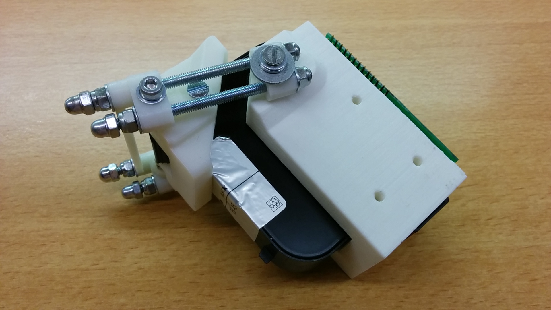
The HP45 is a 600DPI, 300 nozzle printhead made by HP. It is old enough to be controlled with fairly simple control circuitry, but new enough to be fast and accurate. More information on the HP45 can be found here. This page is about a certain challenge that arose when hacking the HP45. How to properly interface with 52 individual contacts on the back of the HP45. The pads are copper, so soldering would have been an option. However soldering would be a big risk. One mistake and the HP45 would be broken. Also if the HP45 needs to be replaced, no easy solution would exist. A more permanent solution was made. A breakout circuit with spring contact pins and a 3D printed carrier to hold the printhead.
[ezcol_1half]
[/ezcol_1half] [ezcol_1half_end]
[/ezcol_1half_end]
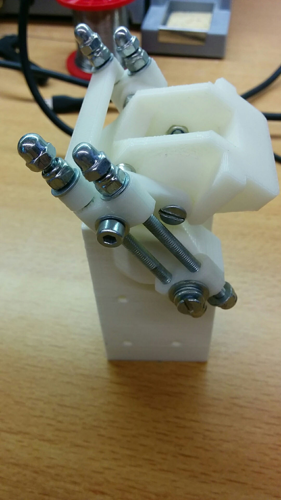
Carrier
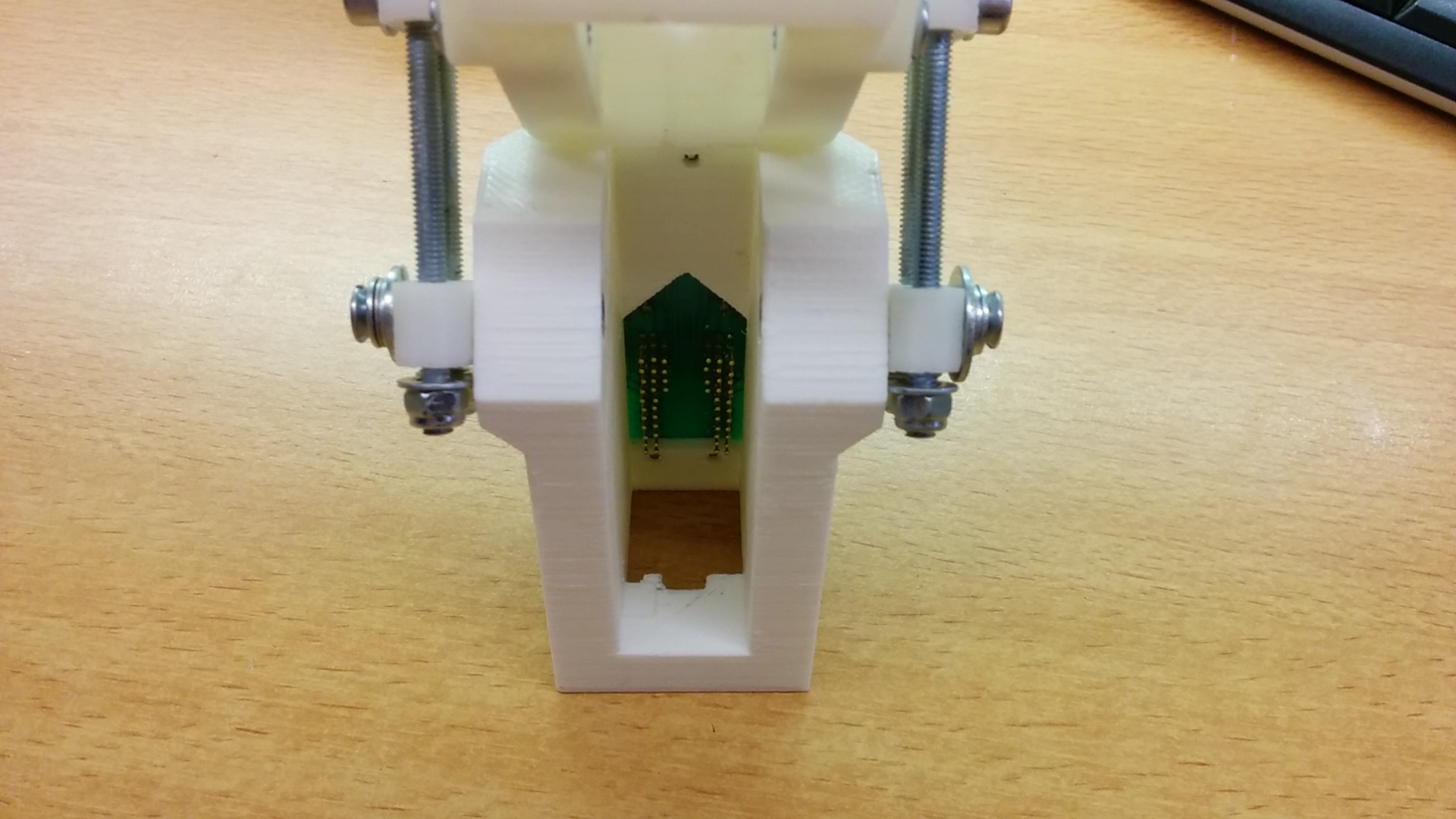
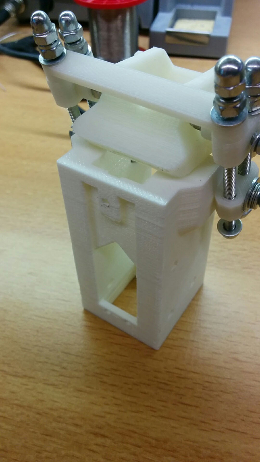
The carrier is the part that holds the actual printhead. This design is 3D printed and has a latch mechanism that can open without tools. The design consists of 9 3D printed parts that require no support material. There are 3 holes in the back of the carrier to which the PCB mounts. These holes need to be threaded with M3 thread using a bolt. Other material include:
- 2x M4 threaded rods 75mm;
- 2x M4 threaded rods 68mm;
- 12x M4 self locking nuts;
- (optional, 4x M4 cap nuts);
- 2x M4 18mm bolts;
- 2x M4 25mm bolts;
- 2x M4 16mm countersunk head screws;
- An assortment of M4 washers (varies, 10-20)
- 3x M3 12mm screws to mount the PCB.
I currently have no assembly guide. If there is a lot of demand, I can make one.
[ezcol_1half]
[/ezcol_1half] [ezcol_1half_end]
[/ezcol_1half_end]
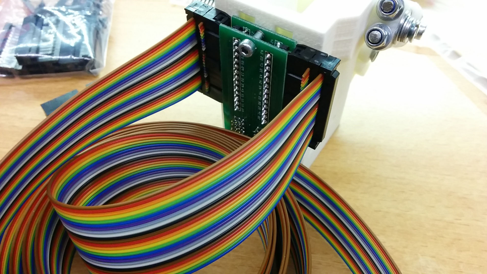
PCB
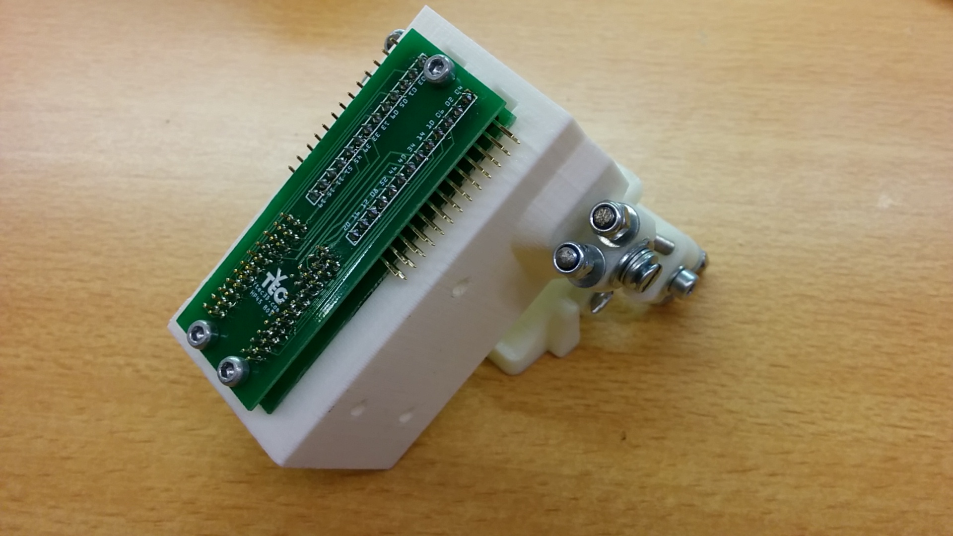
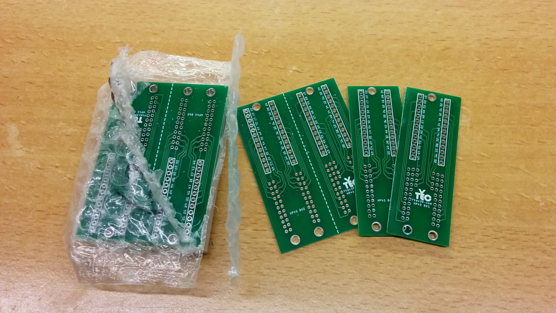
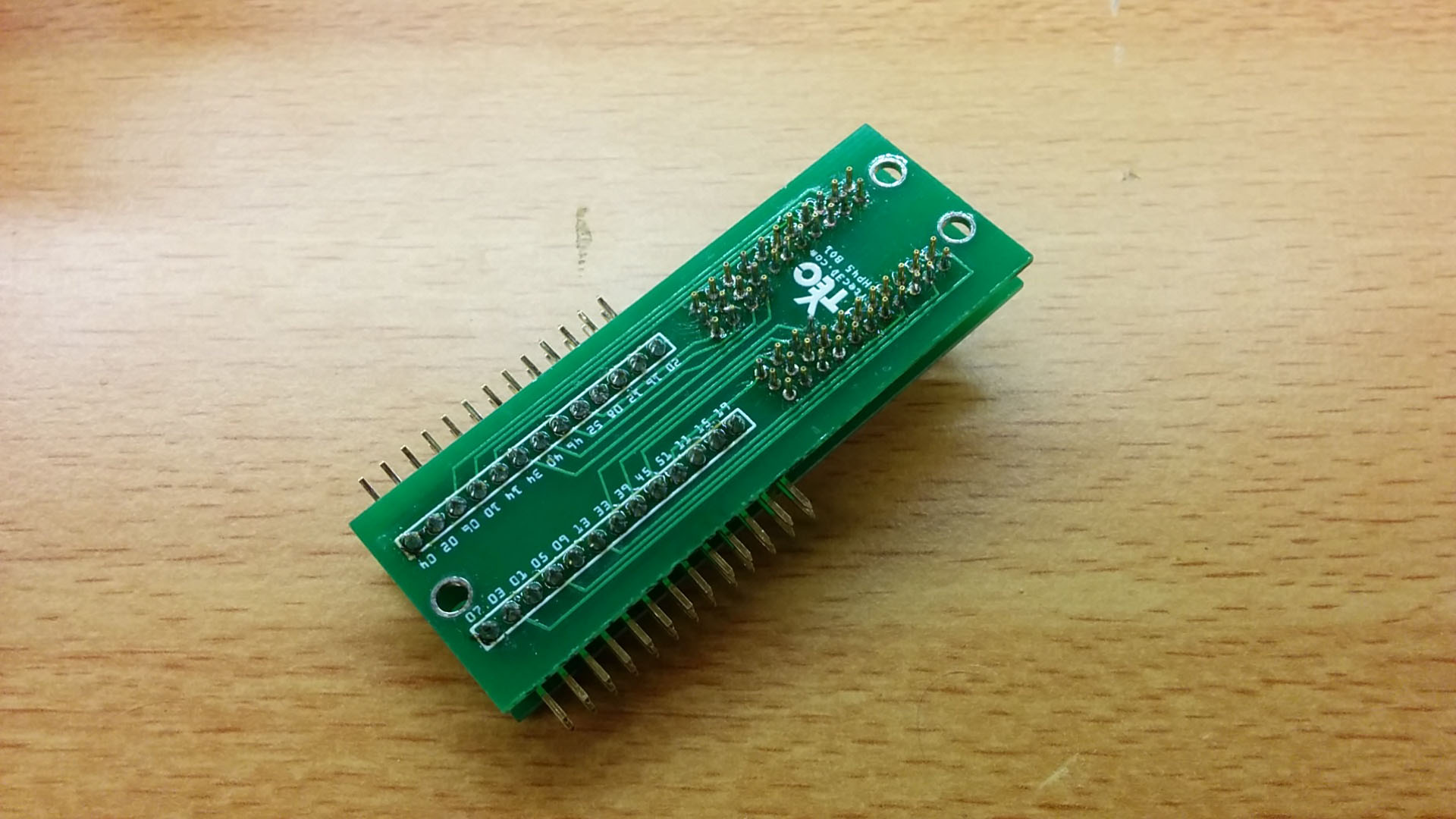
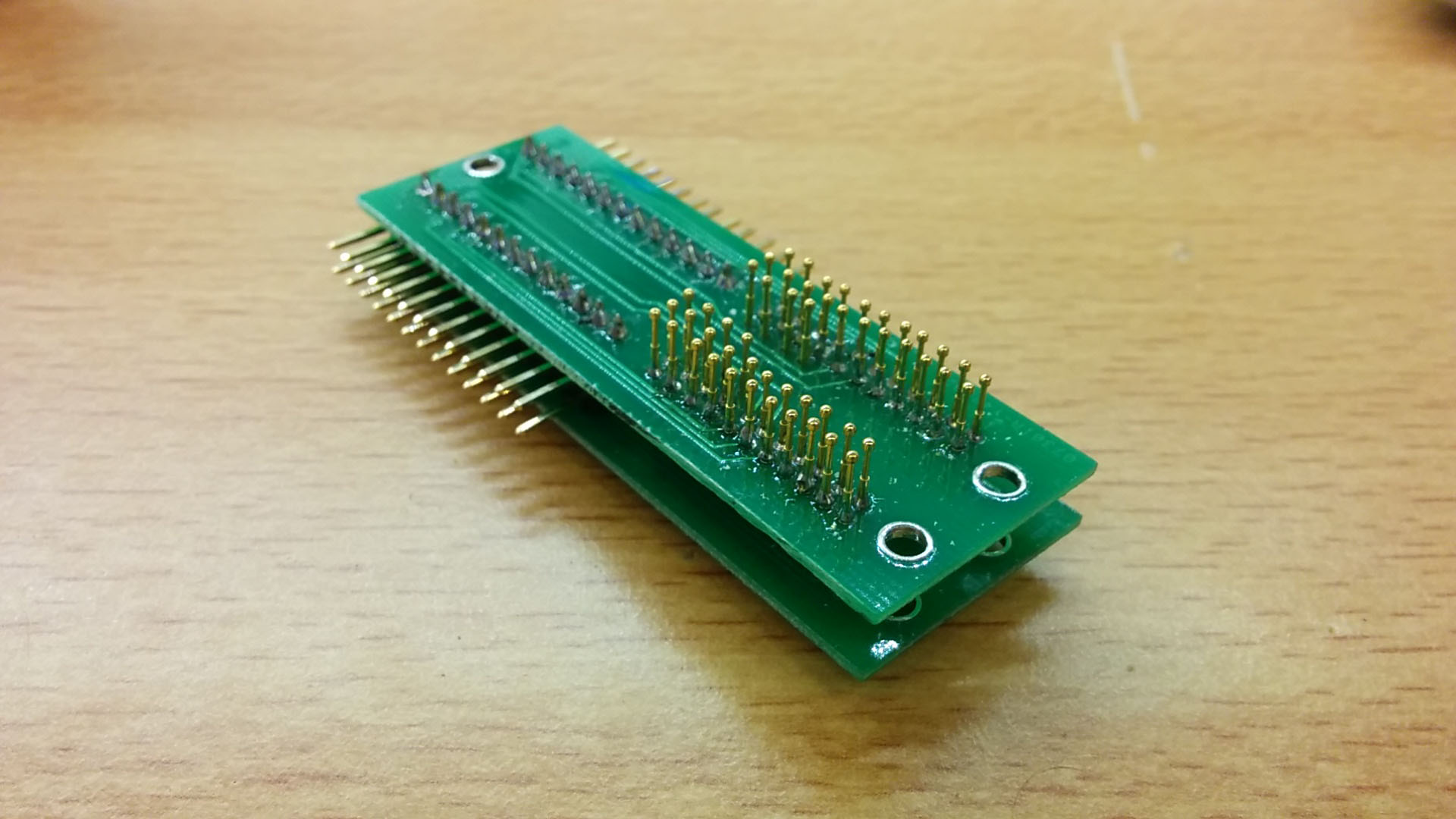
The biggest challenge to the design is the incredibly tight pin spacing (roughly 2mm) combined with a huge number of contacts (52). In some places, there are 3 rows next to each other. An attempt was made to make a single board with all the pins, but it proved too difficult to design. A different design was made. One with 2 PCB’s on top of each other. This has the added benefit of providing additional support to the spring contacts and prevent them from bending. The breakout board breaks the HP45 pins out to two 2×13 headers, one on either side. This gives the 52 pin total. Each of the 2×13 headers can be connected with through a 26 pin ribbon cable header.
The PCB itself is 50x70mm. This PCB can be cut in half to get two 25x70mm boards. The boards have a silkscreen side with the markings ‘HP45 B01’ and ‘HP45 B02’. Both of the boards need to face away from the HP45 with the silkscreen. ‘B02’ needs to be closest to the HP45, ‘B01’ furthest. The distance between the 2 board should be around 5mm, or the width of 2 right angled headers stacked on to of each other. The other parts are 4x 13 pin right angled headers and 52 spring loaded contact pins (example). The maximum diameter of the contact pins is around 0,8mm. Needle tips are not advised since the points can cut into the copper contact pads. On each of the right angled header pins is a number that corresponds to a contact on the HP45. On the ‘B02’ the right angled header needs to be on the side of the silkscreen, the ‘B01’ needs the header on the opposite side.
Soldering spring contacts is not hard, but a few things need to be considered:
- Before soldering it is wise to test fit a single board on the carrier. This way the alignment of the spring contacts and the contact pads can be checked.
- Solder the spring contacts so they are retracted around 50% when the printhead is in place. This distance can be achieved by mounting the PCB and the HP45 in the carrier and pushing the spring contact in before soldering.
- When soldering spring contacts, take care not to solder the seam between the static and moving part, and also to not solder the back. Getting solder in either will ruin the spring contact.
- Keep the spring contacts straight while soldering. If the spring contacts are crooked, they might not properly make contact with the HP45 printhead.
[ezcol_1half]
[/ezcol_1half] [ezcol_1half_end]
[/ezcol_1half_end]
Using it
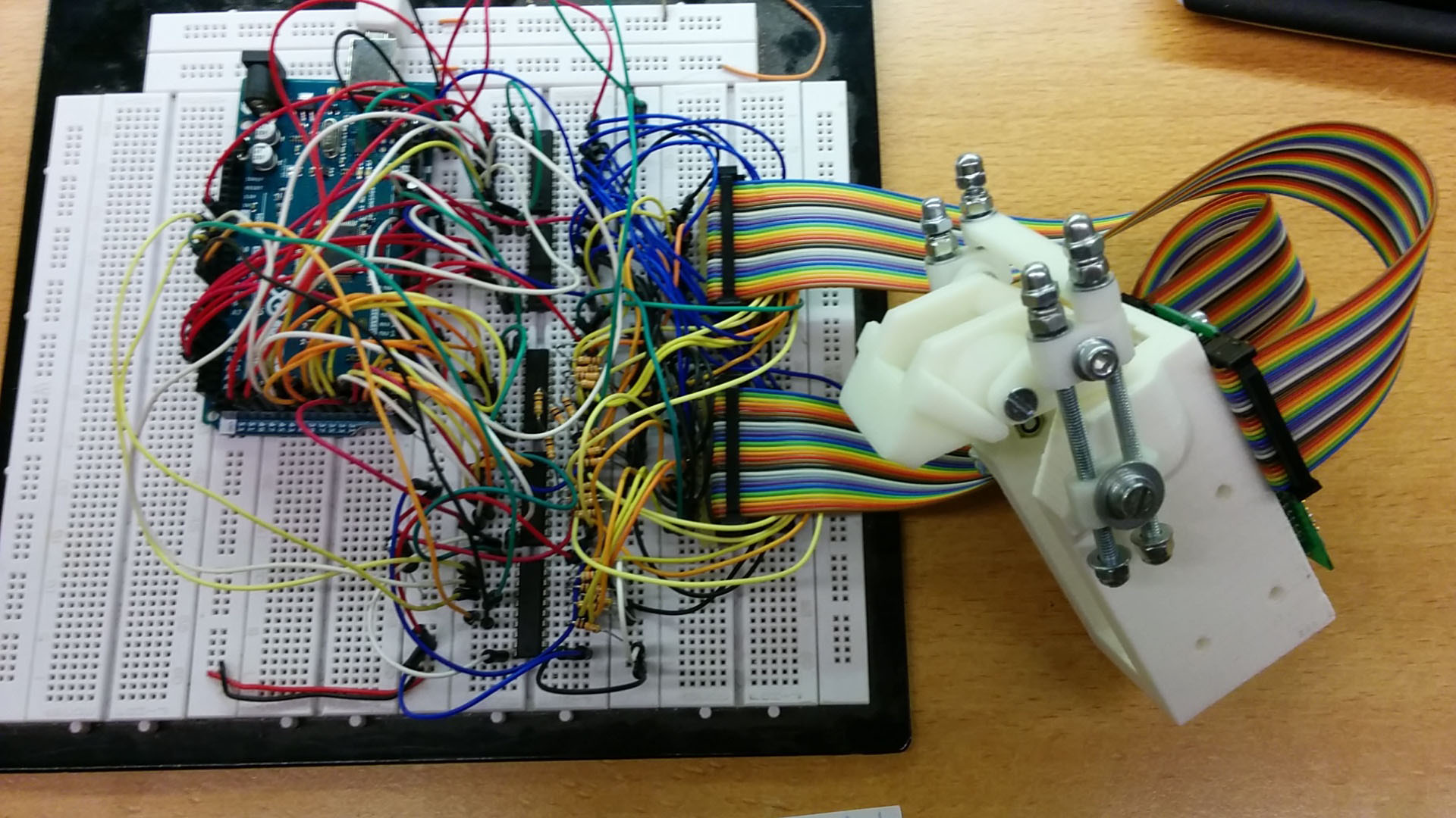
Before connecting, it is wise to adjust the carrier latch so it properly clamps the HP45. It might be somewhat hard to get the HP45 in the carrier. This is normal. The design was slightly too tight. Alignments should have been checked before the spring contacts were soldered. The two 2×13 headers on the side can be used to connect the breakout to any other PCB. I used an adapter to get the two 26 wire ribbon cable to a breadboard where I did most of my own experiments, but a ribbon cable can be connected to anything.
[ezcol_1half]
[/ezcol_1half] [ezcol_1half_end]
[/ezcol_1half_end]
Get your own:
I currently have no shop, but I do have a small stock of breakout PCB’s. If you want one you can contact me through the contact form. You can also download the files below and manufacture them yourself. No hard feelings.
License

The project described on this page is licensed under the Creative commons – Attribution – ShareAlike license.