Hacking the HP45

Powder and inkjet printing
User avatar
dragonator
Site Admin
Posts: 597
Joined: Fri Aug 14, 2015 4:48 pm
Location: The Nethelands
Contact:

Re: Hacking the HP45

Post by dragonator »

And a very quick followup.

The capacitor is now 1uF or 10x as small. I also patched some small things in the firmware. 99 now means a counter reaching it's limit. The results are interesting to say the least. All nozzles that were broken as 0 before are still broke, but some are more broken than others. I have a few nozzles showing up as 17 and 22, where 5-7 is now functioning. This means that they still have some continuity, but not by a long shot as much as they should have.
Nozzle testing screen cap 2.JPG
Nozzle testing screen cap 2.JPG (79.61 KiB) Viewed 18188 times
Wonko
Posts: 110
Joined: Sat Aug 15, 2015 8:13 pm

Re: Hacking the HP45

Post by Wonko »

Amazing work. Great fun to follow. Keeping fingers crossed for all further findings.
User avatar
dragonator
Site Admin
Posts: 597
Joined: Fri Aug 14, 2015 4:48 pm
Location: The Nethelands
Contact:

Re: Hacking the HP45

Post by dragonator »

I started on a controller for the printhead. I was not planning on getting this far today, but once I started I could not really stop. I still need to do some checking, but the basics are here. If I am happy, I will order it after next weekend. The controller has a direct connection to the HP45 via the same setup of pogo pins and 2 PCB's as the previous version, but this one has a lot more on board to control the printhead. There is no real intelligence on the board, only drivers and pin reducing measures. The size of the whole board is 75x80mm, so 75x40mm per halve.
HP45 breakout board Oasis test 1.png
HP45 breakout board Oasis test 1.png (218.19 KiB) Viewed 18173 times
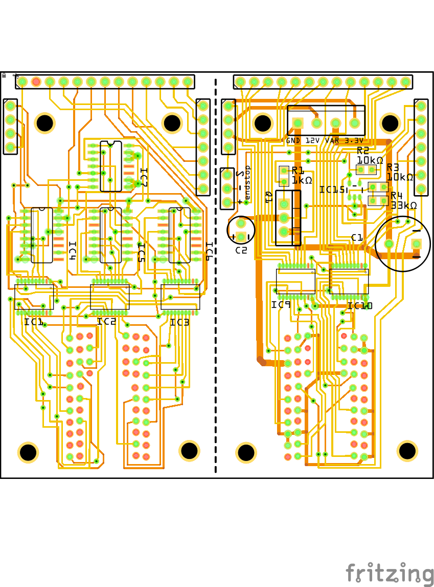
Signals and power enter on the top. There is a 26 pin header for signals and a screw terminal for power. The 2 rows of headers on the side are for signals that need to travel between the 2 layers of boards.

The left side board is for the addresses and is mounted closest to the printhead. It has an array of 4017 and 4081 chips to get the 22 pins controlled with only 2 control pins. A reset on the 4017 will set the address to 1, and every clock pulse will make it go to the next address. Under the 4017 chips are the TLC59213 chips, this time SMD version. The clock and clear still control when they are triggered.

Moving to the right halve. This side sit away from the printhead and houses some of the bigger components. There is a screw terminal with ground, 12V, a variable voltage for the primitives, and a 3.3V line. I plan on running all future experiments with a DUE. on the left is a 3 pin header for an endstop, for if this version of the controller every makes it on a printer. Moving to the middle there is the mosfet to interrupt the ground and the nozzle condition circuitry. This time the comparator is an LMV331, because the LM311 cannot be driven with 3.3V. Downward are the 2 primitive drivers and the rest of the circuit for the pogo pins.

Also snaking through the circuit are the 10x resistor and the thermal sense resistor. I do no conditioning to these signals because I am not yet certain what I want to do with it. I recon that I get the 10x resistor so I can do the accurate stuff elsewhere. I can calibrate the measurements on the 10x resistor if I need to.

There is no schematic yet, but once I order the parts I will make one.
Philipp
Posts: 34
Joined: Sat Mar 12, 2016 10:55 am

Re: Hacking the HP45

Post by Philipp »

Hello,
that is a great success, I did not expect you to come so quickly. I can not wait to test the systems.

Best wishes
Philipp
EngieR
Posts: 2
Joined: Wed May 18, 2016 11:13 am

Re: Hacking the HP45

Post by EngieR »

Hi,

I just found this forum and I must say that I'm really interested in this and amazed how far you guys are already. I can really use these schedules/notes! About the updated PCB's: the IC's you mention on the figure above, are that the previously mentioned TLC59213? If so, why are there more now? What is the extra use of all those components? (I'm sorry, but on the electronical level I'm really new, but on the mechanical level I'm good)

And on the image on page 8 I see some capacitors and resistors that are not in the schedule, so these are not needed?

Some questions about the components:
-What is the official name of the thing between the PCB's where you connect your 26pins flat cable to? I'm trying to buy all the components but I don't know what the official name of that one is. (Again sorry for the low electronic-knowledge)
-Where/how did you order your PCB'S?
-How far do you solder in the pogo pins? I can't really see an edge that has to touch the PCB to control the distance on the ebay-image.

I really would like to help out, I've had something similar in mind, so this forum comes in really handy!
User avatar
dragonator
Site Admin
Posts: 597
Joined: Fri Aug 14, 2015 4:48 pm
Location: The Nethelands
Contact:

Re: Hacking the HP45

Post by dragonator »

Hello,

The first PCB on the early pages is only to make a direct connection with the HP45. All of the 52 contacts have a pin on the PCB. All high power signals need to be made elsewhere. The newer version you see above is to properly control the HP45. It has all high power circuitry on board. All it requires is low voltage microcontroller signals. There are still 5 TLC59213's on the board, but there are other components as well to reduce the amount of pins that need to go to the controller.

The resistors were taken out of the design because they were not necessary. The capacitors are still required and will be added to a schematic once I have more updates.

-The thing connecting the PCB to the flat cable is 2 parts, it is a 90 degree header on the PCB, and a 26 pin cable header on the flat cable.
- I got them from a manufacturer in China, but if you really want some, I still have half a dozen left.
- There is no edge. How far they are soldered depends on where they are mounted. In my case I too the HP45 holder with the PCB, and soldered it in with slight pressure against the HP45.

I want to have said this. If you are still new with electronics, I advice against starting with something like this. This is not rocket science, but there are quite a few things with some difficulty about this type of electronics. That said, you are welcome to try and help, I just wanted to give the warning.
User avatar
dragonator
Site Admin
Posts: 597
Joined: Fri Aug 14, 2015 4:48 pm
Location: The Nethelands
Contact:

Re: Hacking the HP45

Post by dragonator »

I modified the circuit so the addresses are now attached to 4017 decade counters. Only 1 address needs to be on at a time, and the order is always the same, so there is no good reason to have all 22 address pins connected to a microcontroller.

The 4017 chips reduce the pin count from 24 (clear, clock and 22 addresses) to 4 (clear, clock, 4017 clock and reset). If I trigger the 4017 reset, the address will jump to 1. Every 4017 clock pulse will progress it to the next address. At 22 it stops and needs to be reset again. This has the added benefit of slightly lightening the load on the firmware. I no longer have to calculate which of the 22 address pins need to be high. I just pulse after each primitive set.

The circuit was tested and seems to operate fine. This is also how I am designing the address handling on the controller.
Now with added 4017 chips (and a 4081 to make it work)
IMG_20160518_203213.jpg (342.43 KiB) Viewed 18133 times
HP45 Mega connection diagram 4.png
HP45 Mega connection diagram 4.png (439.76 KiB) Viewed 18133 times
Wonko
Posts: 110
Joined: Sat Aug 15, 2015 8:13 pm

Re: Hacking the HP45

Post by Wonko »

You can save yourself at least four chips. There are source drivers out there with serial input. Simply clock in the first bit, then shift, latch, shift, latch, etc. . This one is 8 bits with also 500mA, but i recall that there are 10, 14 and even 64 bits available.

http://ww1.microchip.com/downloads/en/D ... ic5891.pdf

or

http://www.emesystems.com/pdfs/parts/A6810.pdf
User avatar
dragonator
Site Admin
Posts: 597
Joined: Fri Aug 14, 2015 4:48 pm
Location: The Nethelands
Contact:

Re: Hacking the HP45

Post by dragonator »

4 chips is significant savings where they need to be. Also these are used on the address side, so they only have to source, but not provide that much current.

Many thanks for the great suggestion. I will investigate further and see if I can find chips to test with on my breadboard.
Philipp
Posts: 34
Joined: Sat Mar 12, 2016 10:55 am

Re: Hacking the HP45

Post by Philipp »

Hi Guys,
I have been following the development with great interest. If I have understood correctly, it might be possible to limit the board to the width of the HP45.
That would make it possible to place multiple print heads next to each other, for several colours or to cascade them.
Post Reply