Home › Forums › 3DP printing › Step 2: conveying powder
- This topic has 3 replies, 2 voices, and was last updated 9 years, 1 month ago by
ezrec.
-
AuthorPosts
-
March 1, 2015 at 7:03 pm #2178
dragonator
KeymasterWhile step 1 of the next gen 3DP is not yet complete (I have a few backup plans ready), there is still a few other things I need to do for the design of the next printer. For reasons that will become clear in a later stage, I need to convey powder diagonally up. My first idea for this: a 3D printed auger.


To my surprise, the screws work without too much resistance and at a decent feedrate. The powder input is not ideal, so under better circumstances it might be even more.
With the powder screw working, I can continue with the new design.
March 12, 2015 at 7:10 pm #2191ezrec
ParticipantInstead of conveying powder up (with the associated feed issues to the auger) why not convey the powder down?
If your design requires conveying up, attach a cell phone vibration motor (eccentric weight) to the feed bin to keep the angle of repose of the feed material as low as possible.
March 14, 2015 at 7:41 pm #2194KeymasterI most definitely considered that, but hear me out.
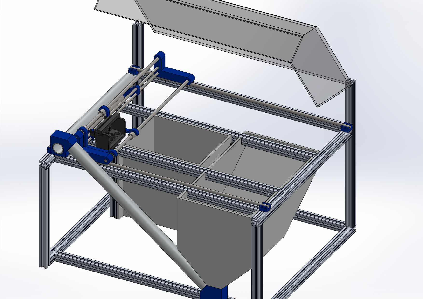
For a next printer I am stuck with an idea, of making a printer that is as user friendly as possible. For this you need a hopper (like you suggest, or as I will show below), because preparing a powder bed takes skill. The problem with a top feeding hopper (and why I consider what I have for an idea) is that it takes a lot of vertical space. Combine it with pistons, and the printer needs to be massively tall.
Here is my idea. A printer that has a hopper and piston design that requires no lead screws and guide shafts (based on cables and springs) and a side hopper next to the build platform. Screws convey the powder diagonally up and over the build area, where the spreader can pick it up (with a small opening mechanism). Any excess will fall back down, to the overflow, where a last screw will convey it back to the main hopper. The piston can also open up (like with Zcorps) and the powder will fall down to the overflow, where it too, gets pumped back to the hopper.
I admit this design does have flaws. For one it is more complex than other printers to make. Also, for people that want to experiment with powders, this printer takes forever to clean. To remedy this, I have an idea to make a small piston (with top feeder) that fits in the lowered build platform. This way, you can test small batches. I am still not sure if this is the right way to do it. It is complex and hard for open source to make, but it does offer ease of use like nothing out there.
 March 16, 2015 at 3:30 pm #2196Participant
I have experience with string drive – I’ll see if I can get you a good picture of my ‘grommet drive’ mechanism – it’s a super cheap stepper drive system that gets a good grip on the braided fishing line I use.
Simply put, it’s a large grommet on a brass compression pipe fitting on a stepper shaft.
As for cleanup, I highly suggest a vacuum system – have the bottom section be a MDF sidewalls instead of aluminum rails, with a canvas sheet on the bottom with a port for attaching a shop vacuum hose.
Cleanup is then a matter of turning on the vacuum, and dusting extra powder off the top into the piston chamber, where it falls into the canvas and gets collected by the vacuum.
Or just falls by gravity into a collection bucket.
-
AuthorPosts
- You must be logged in to reply to this topic.