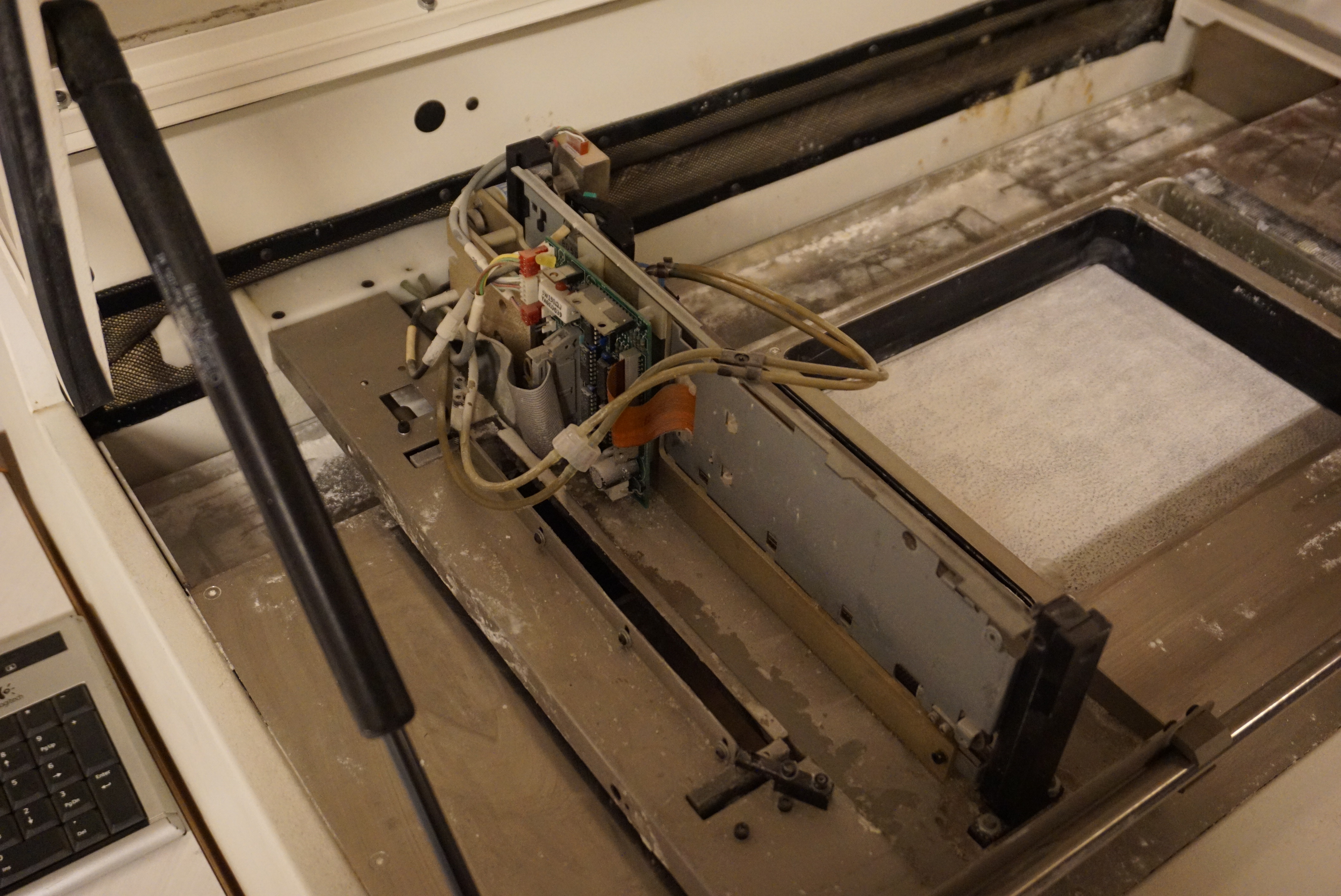
Everything needed to make the Z400 work is working. In March I got the Z400 from Wonko in Germany. Since then I have tested all the power supplies, secured the disc image in case the disc ever fails and added a transformer to run this 115V machine in the Netherlands. I have gotten the inkjet printer part to work, repaired the pistons and made new printheads that printed binder.
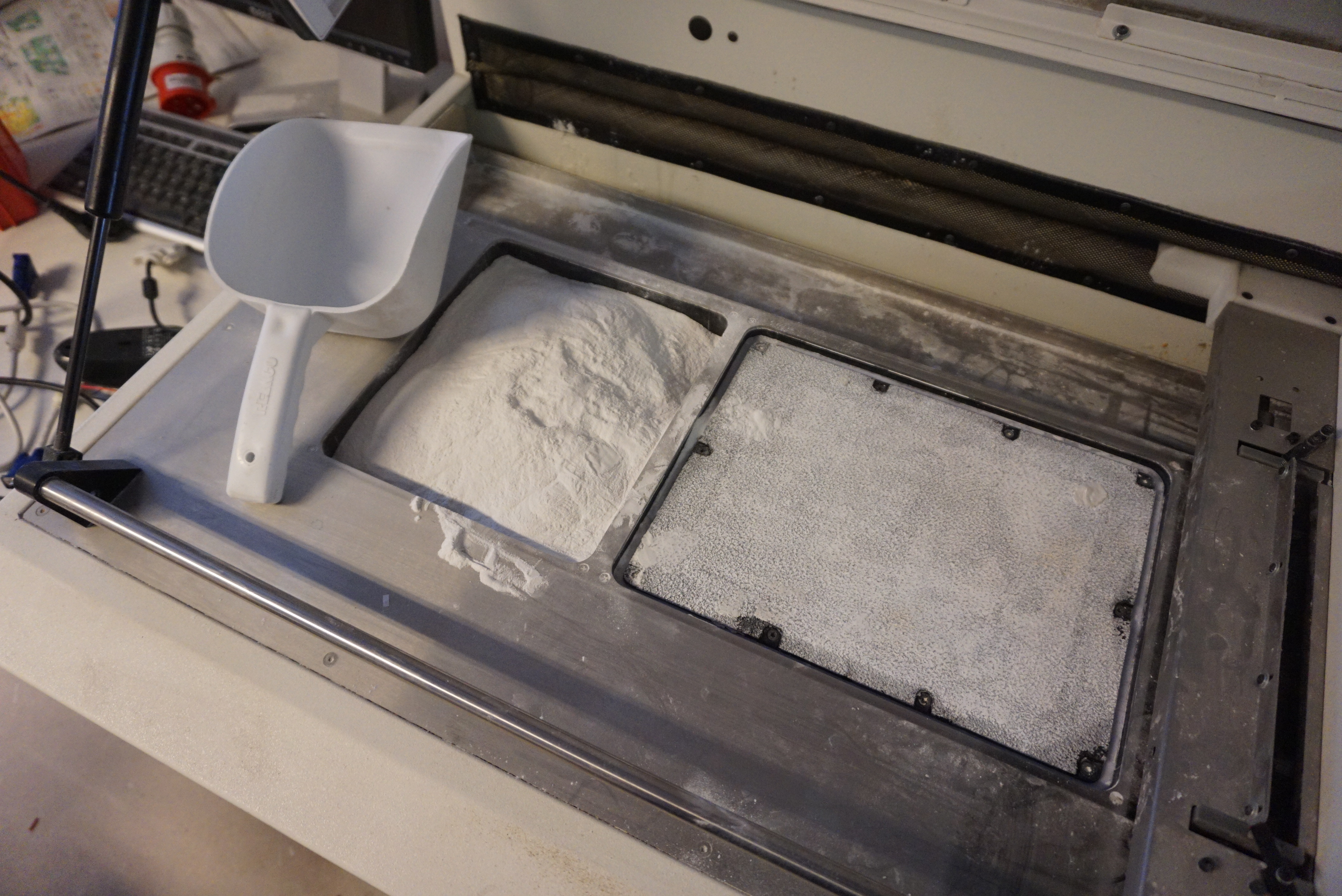
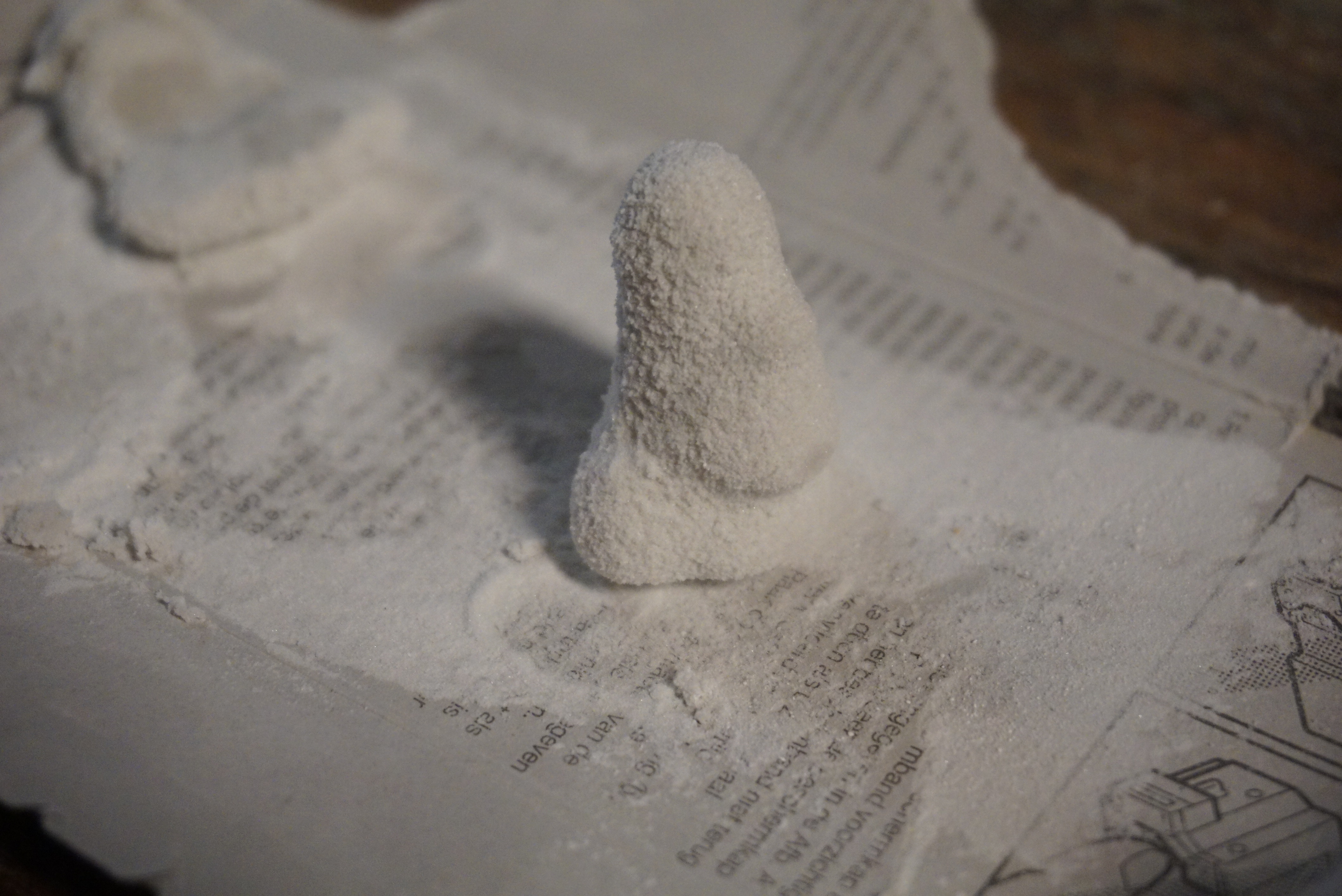
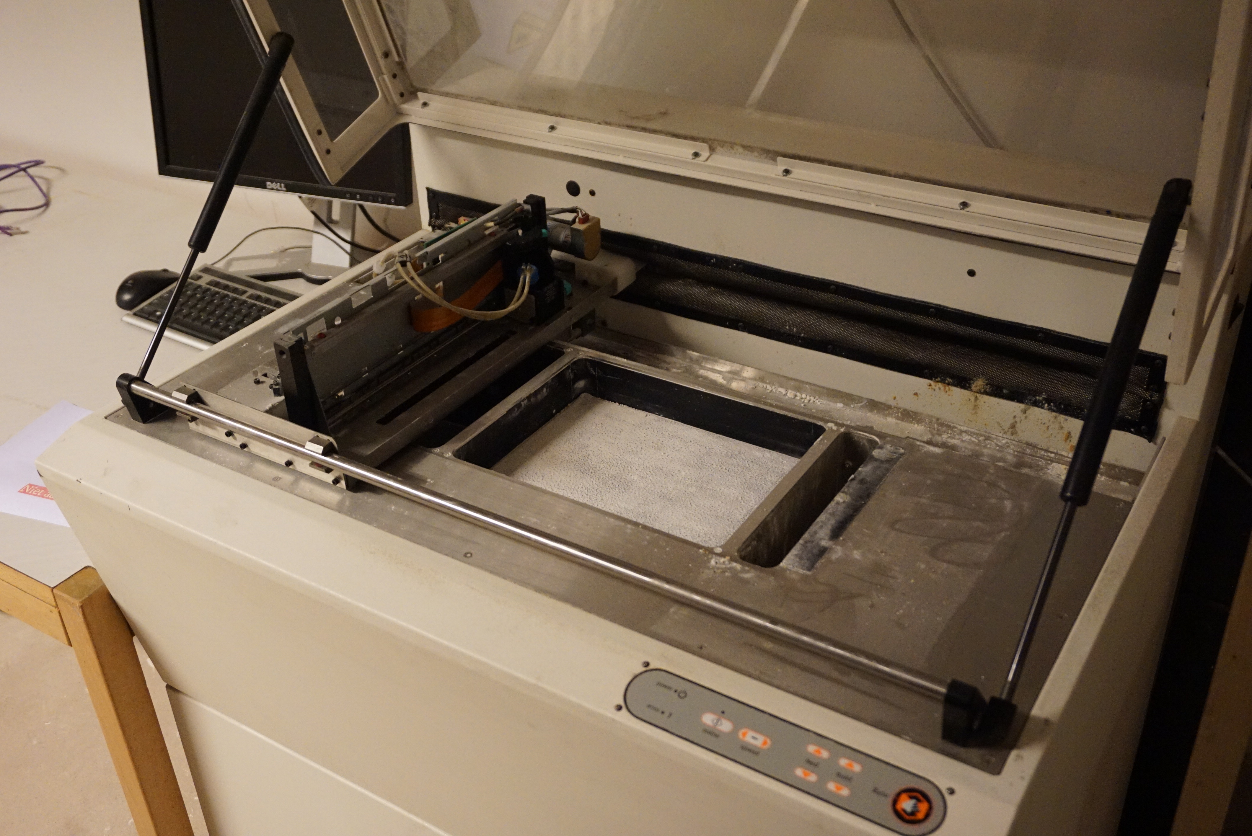
I filled the printer with powder I still had, then I hit ‘3D print’
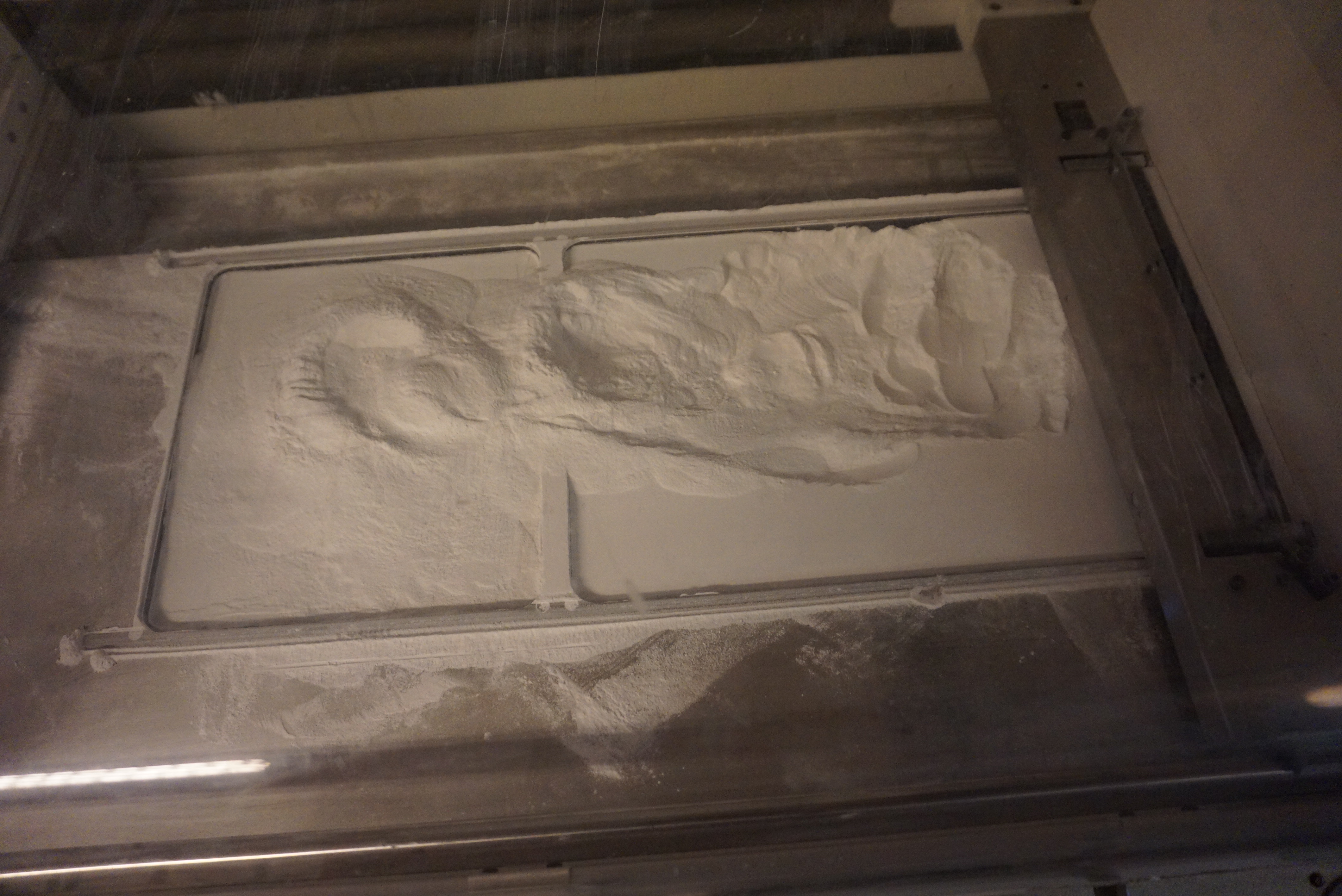
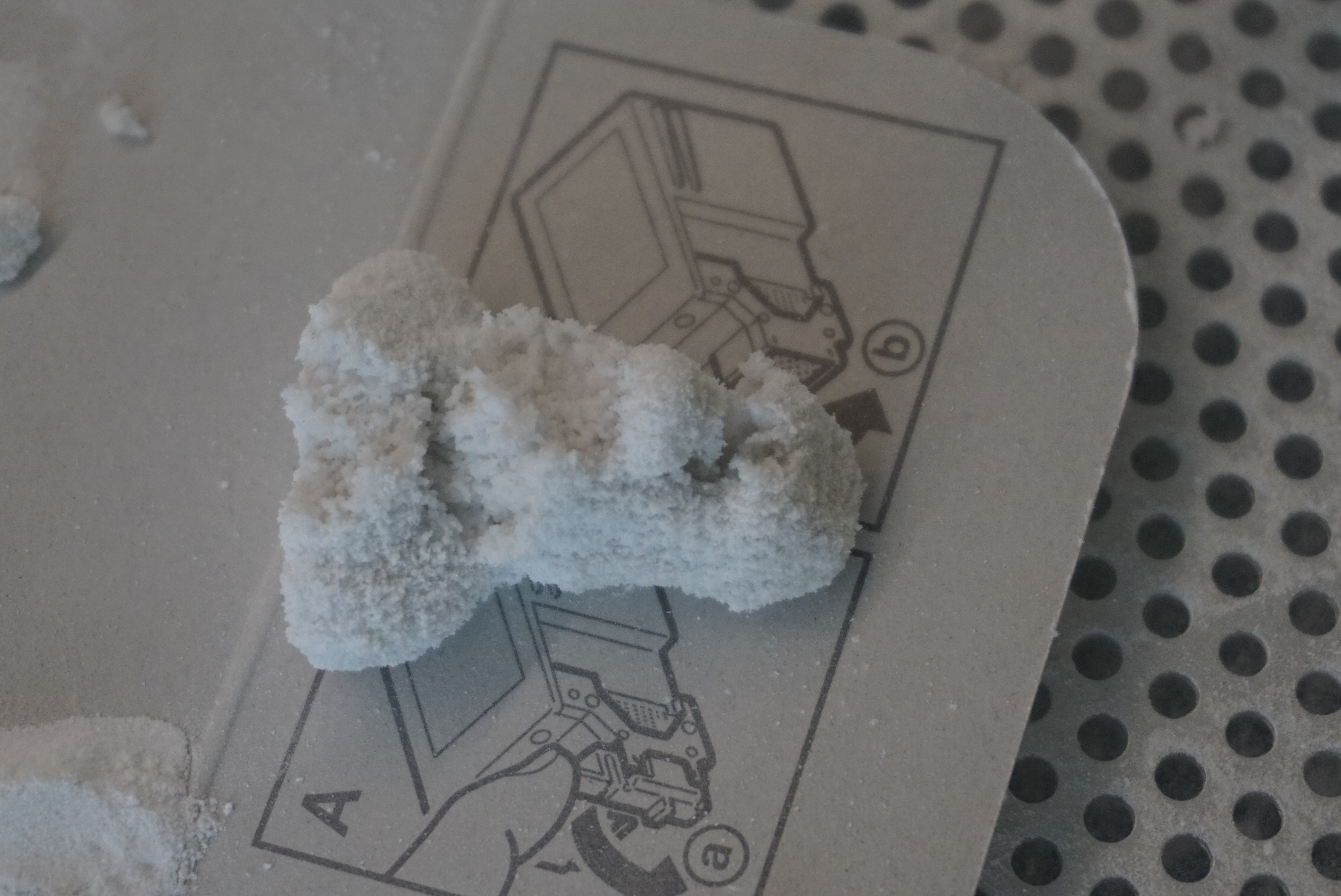
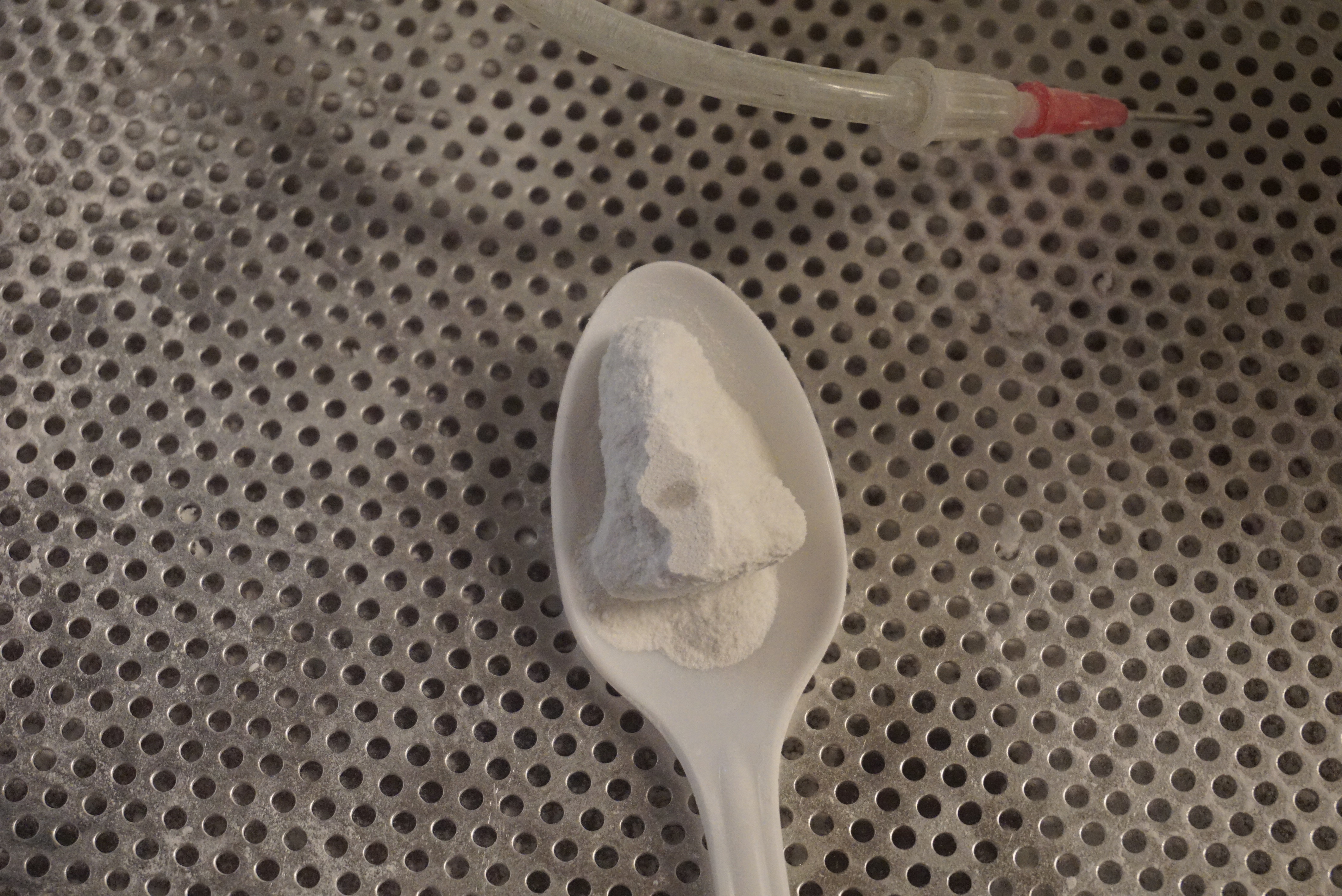
Filling the printerDigging the part out of the powderDisintegrated during depowderingAttempt 2, on a spoonA Moai 3D print in plaster, but not a good one
The printer worked great. Layer by layer I saw a part get made. So far it looked really good. Getting the part out after 30 minutes proved problematic, the part would disintegrate during cleaning. Another print was made, and left for a day to set. Lots of binder leaked into the surrounding unbound powder. I then printed at a lower binder percentage (75%), but was met with the same results.
So the conclusion: Yes printer, no powder. The powder I currently have requires special binders, not water with alcohol I currently have in there. I might still test that powder with the tiny amount of binder I do have, but I will run out quickly. It will be better if I get another powder.
One problem. This machine needs absolutely enormous amounts of powder to print even the tiniest parts (compared to my own printers). Now all of this powder can be reused, but it still needs to be filled. Lets assume buying is no option and I need to make it myself. Obviously I am not going to test powders on a machine that needs 2kg of powder just to print a 2cm part, so I will need another way to test powder recipes. I do have some ideas, but with summer vacation coming up, I will not have that much time to work on it.
The bad news is that Z400 progress will be a bit slower from now on. I have worked hard to get the machine to work, but now I need powder recipes and binder recipes, and while I have some of them, I have yet to validate them, and I would prefer to do that in smaller amounts. HP45 related projects are expected from September onward.
So no worries, I will continue with the Z400, it will only take a few months to get everything ready.
Inkjet printers use inkjet printheads, and the Z-corp is basically a glorified inkjet printer. The printheads for essentially all printers ever are still sold, if only as re-manufactured heads. Logic would suggest that there is a place where I can buy Z400 printheads. Well, sadly, no. Z400 printheads are pure unobtainium. Ludicrously expensive while they were still in production, and basically non-existent now.
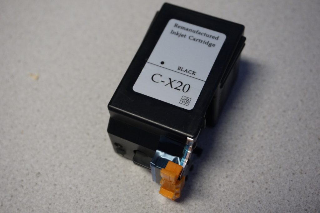
However, the Z400 are basically modified Canon BC-20 heads, and the Cannon BC-20 heads (or at least the BX-20 heads, which are the same) are still being sold. Original ones are not cheap (€60 per head), but re-manufactured, they can be found for under €15. There are a few options for modification.
You can cut open the head and glue in some part inside the printhead. This way you will have less buffer in the head (and no longer have the annoying sponge) but it requires more parts. The other way is what I am going to use. Most of it is based on this site: http://blog.freesideatlanta.org/2011/07/making-print-cartridges-for-z400z402-3d.html
Modifying a printhead
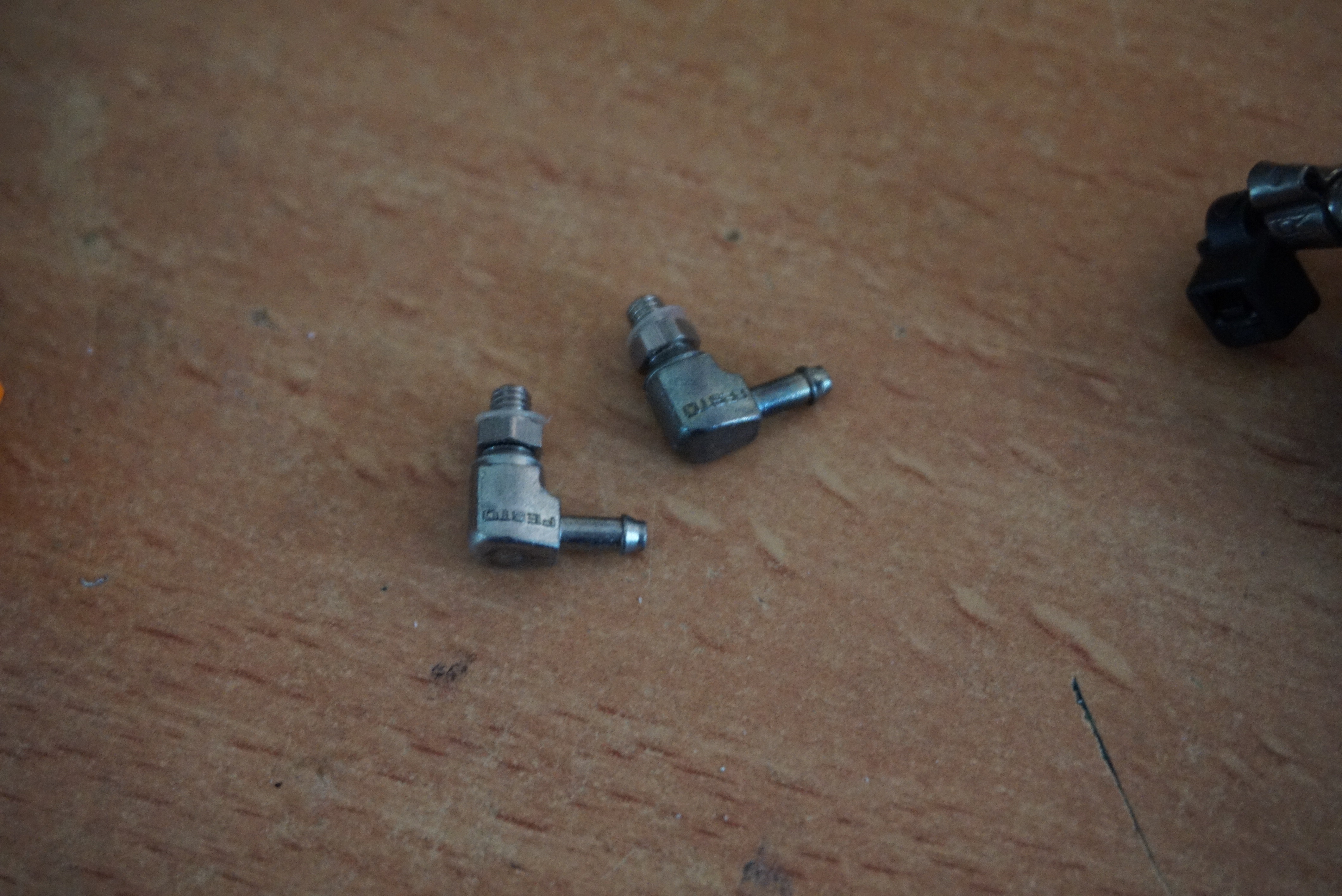
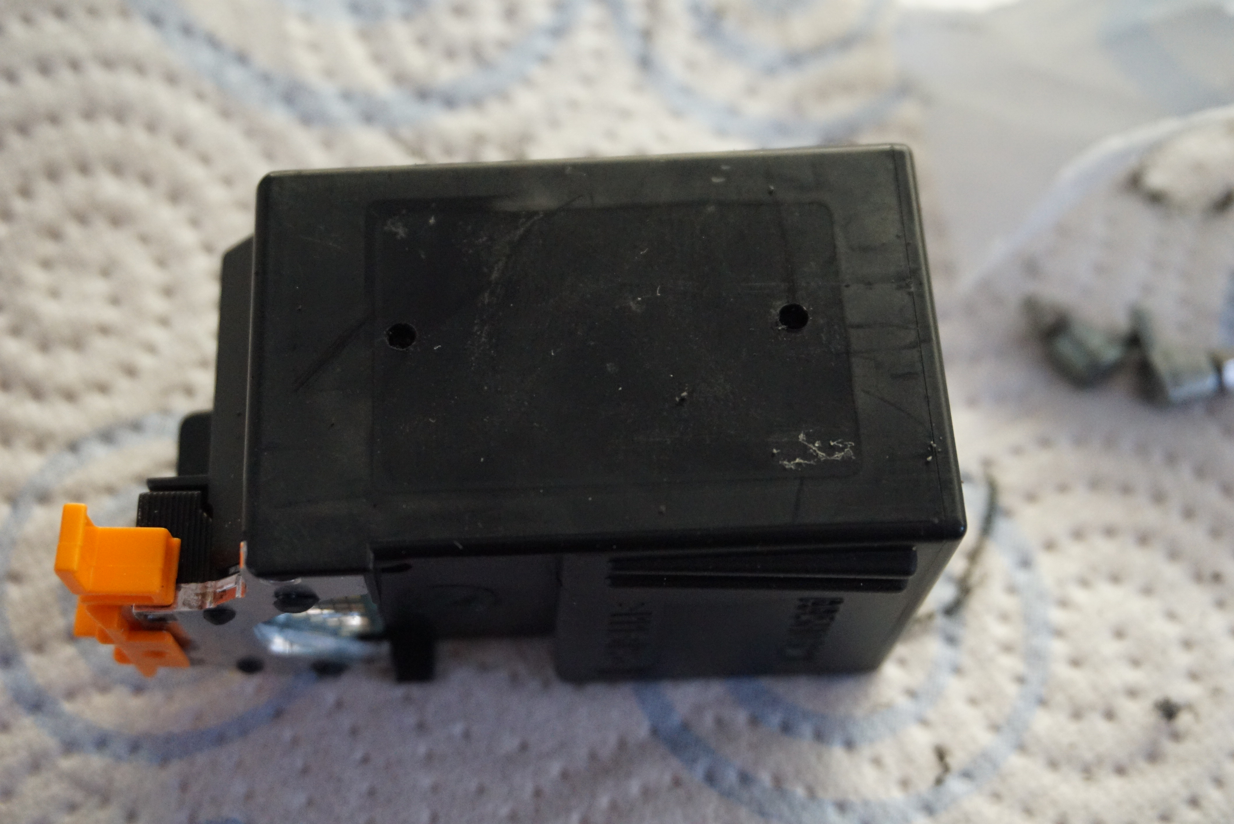
The head I will be using is a Cannon BX-20. I bought BC-20’s but it is all the same. I have also scavenged some barbed fittings from the pneumatic parts junk bin at my work, but any small hose barb will work. A full list of items needed:
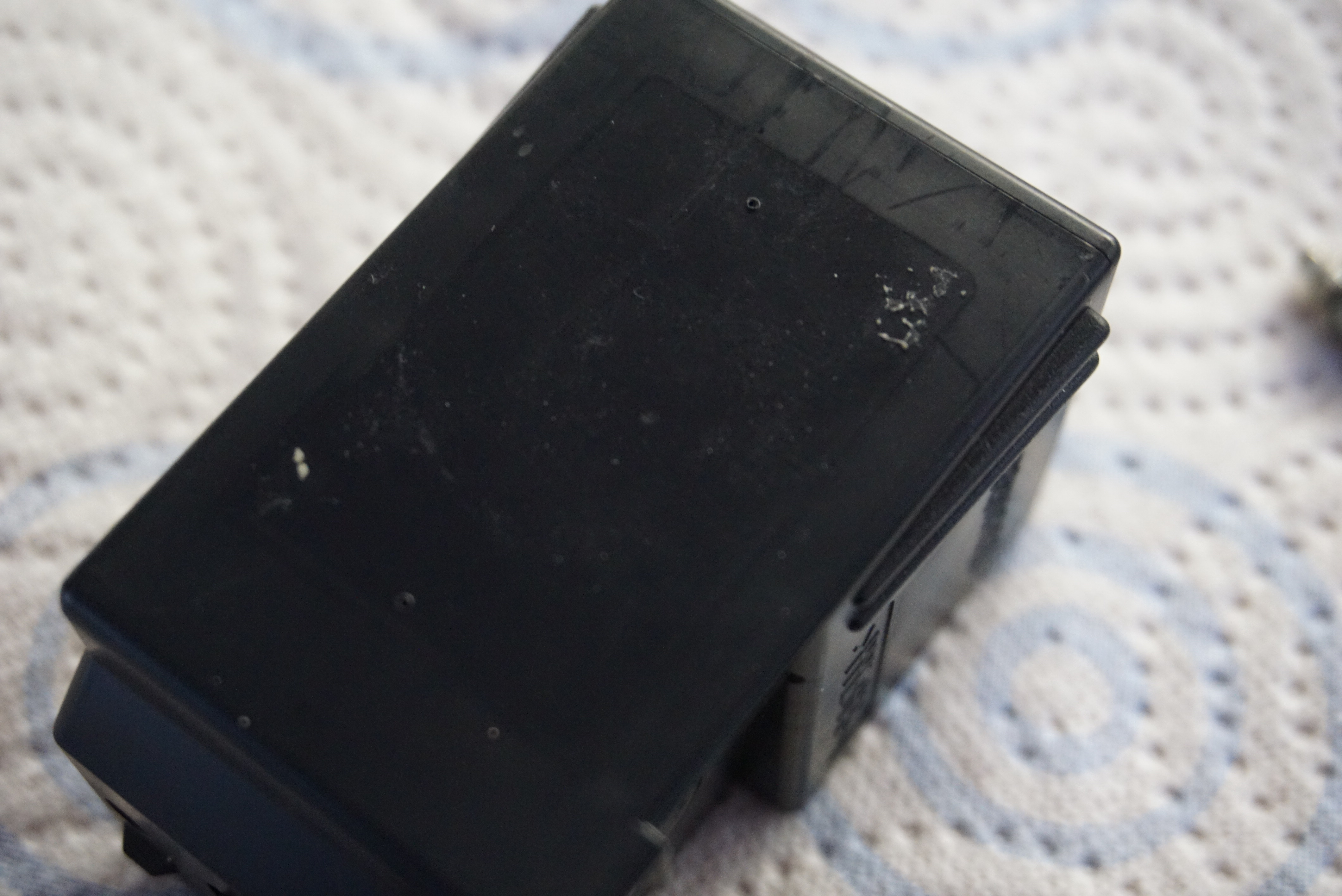
The Cannon BC-20 or BX-20 printhead
2x Hose barb fittings
A drill to match the hose barb
Some sort of glue (I used CA with activator)
A syringe
A tube that fits the hose barb
Some tape of any kind
Running water and a sink (it can get messy)
Festo hose barbsA Canon BX-20 printhead
Two things to note here. One, this is my first BX-20 modification. It is more a rough guideline than an actual guide. If I get requests, I might make a real guide. Two, Do this in old clothes or at your own risk. Inkjet ink is incredibly potent and can be diluted 1000 times and still be pitch black. If you get this stuff in your clothes, it will stay there. If you get it on your fingers, it will stay there (for about a day).
2 hole markings2 fresh holes
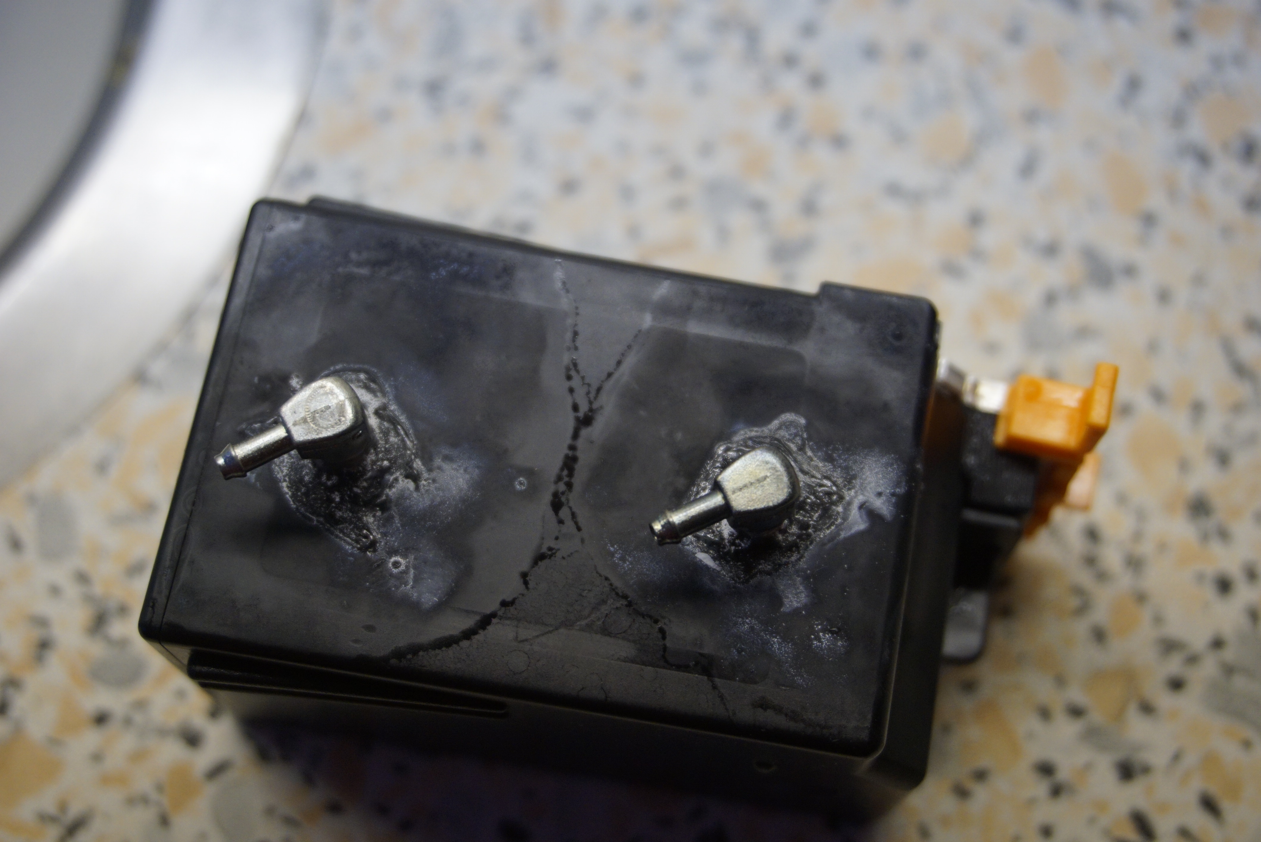
I first started by drilling 2 2,5mm holes in the side of the printhead. One about 1cm from the bottom, and 1 about 1cm from the top. The bottom one is for the supply, the top one for the return.
I then mounted the hose barbs. I use used some CA around the edge of the barbs to make a proper watertight seal around the barbs.
Above a sink with running water, with one of the barbs facing down, I blew air through the other barb to get all of the ink to flow out of the hole. I Filled the head with water using the syringe. I then repeated these steps until the water coming out of the head was clear. Using the same technique as above, I cleared as much water from the head as possible.
Last, an important step not mentioned in any other guide I found. Close the hole at the top. For normal inkjet operation this hole is required, but for CISS, this hole will cause a nice fountain to appear. I simply stuck some tape on the hole to close it.
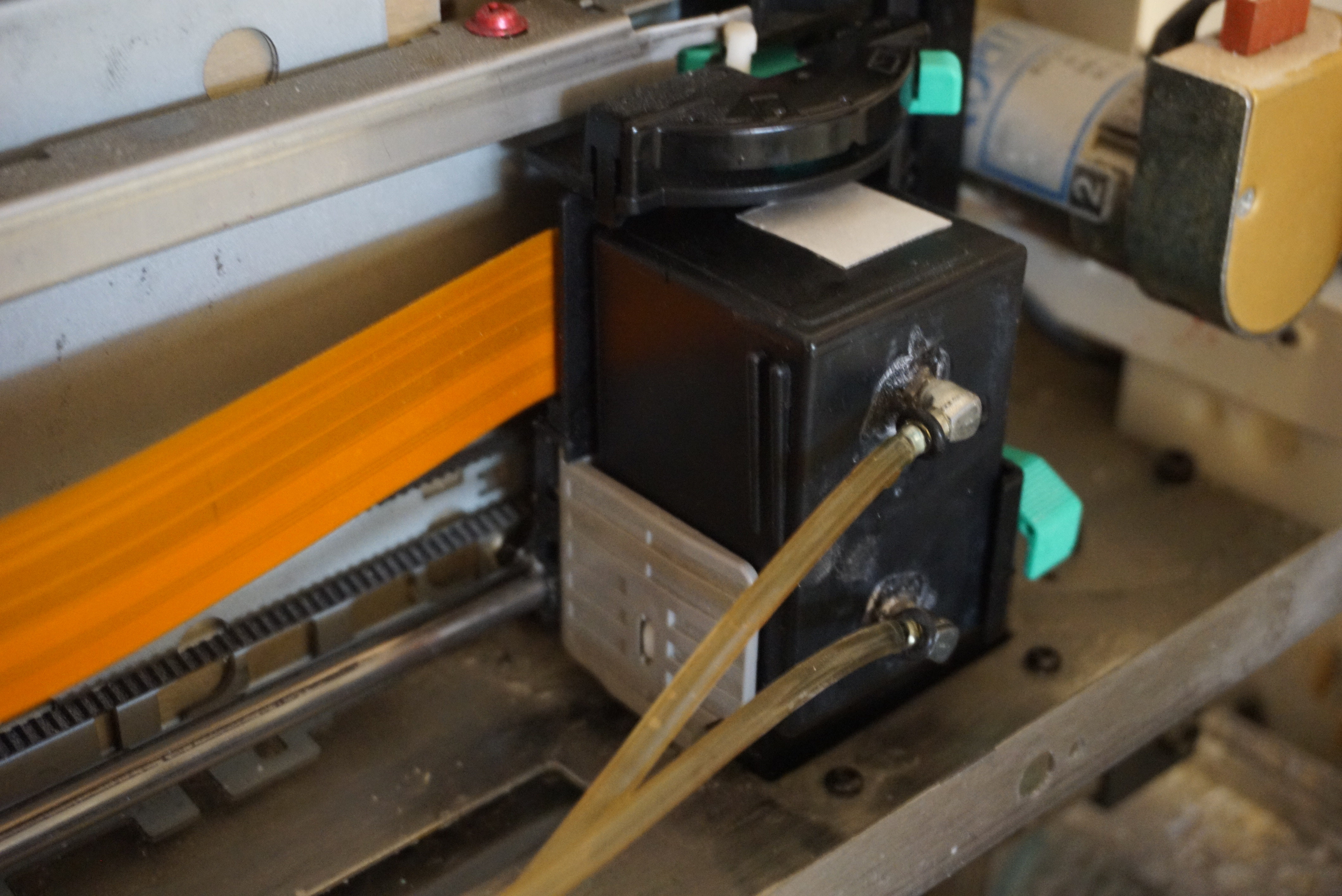
The printhead was now ready for use in the printer.
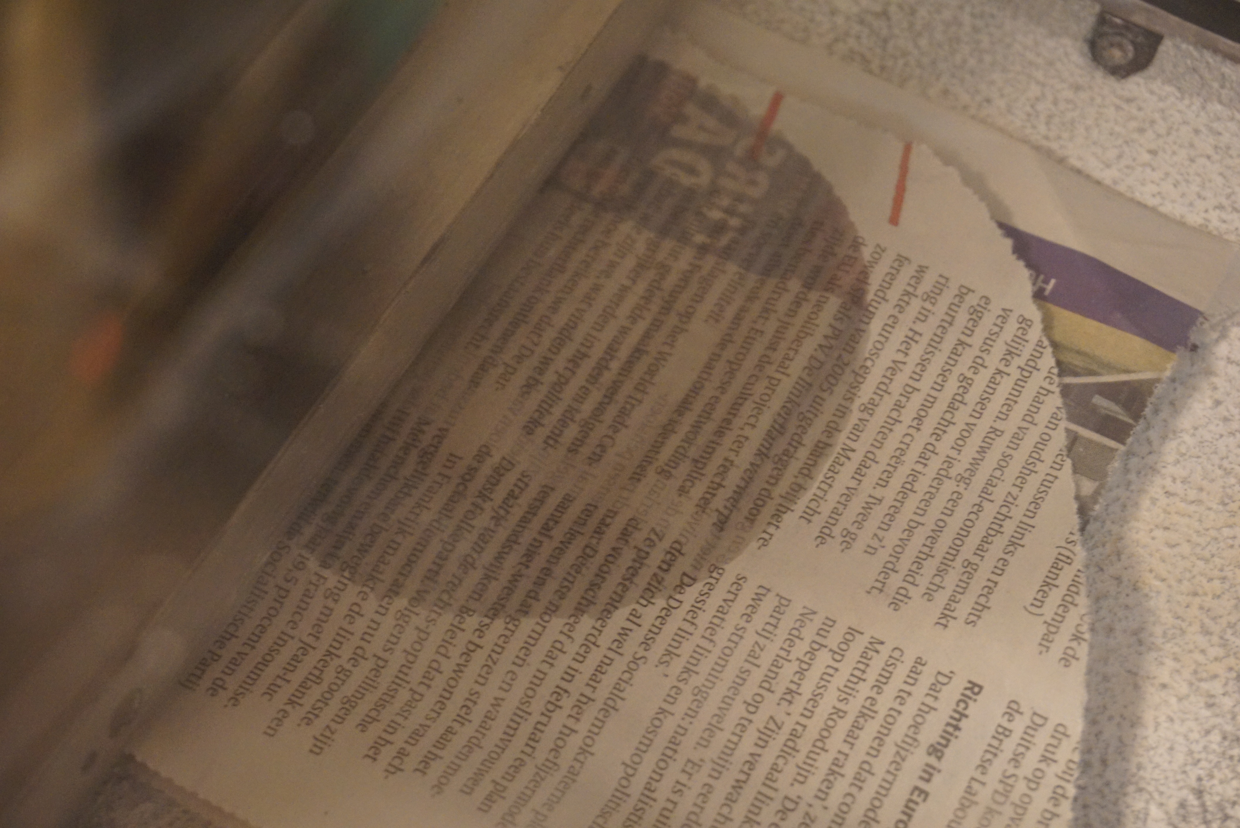
ready for usePrinthead installed in printerA test print on newspaper
With the printheads ready and installed, I can now try and print. Next blog, me trying to print.
Before I start. I still needed to measure the print size of the Z400. It is not in the manual, and I have no other place to share yet. It is exactly US letter size (about 280mm by 215mm) and about 350mm in height. A fairly sizable printer, and about enough for my ultimate goal with a powder printer.
(Edit: The vertical stroke of each piston is around 350mm, but the usable build size for the printer is only 8″ (200mm). They probably made the stroke of the pistons equal, but since the build piston is bigger than the feed piston, the feed piston needs more stroke than build piston.)
Pretty deep
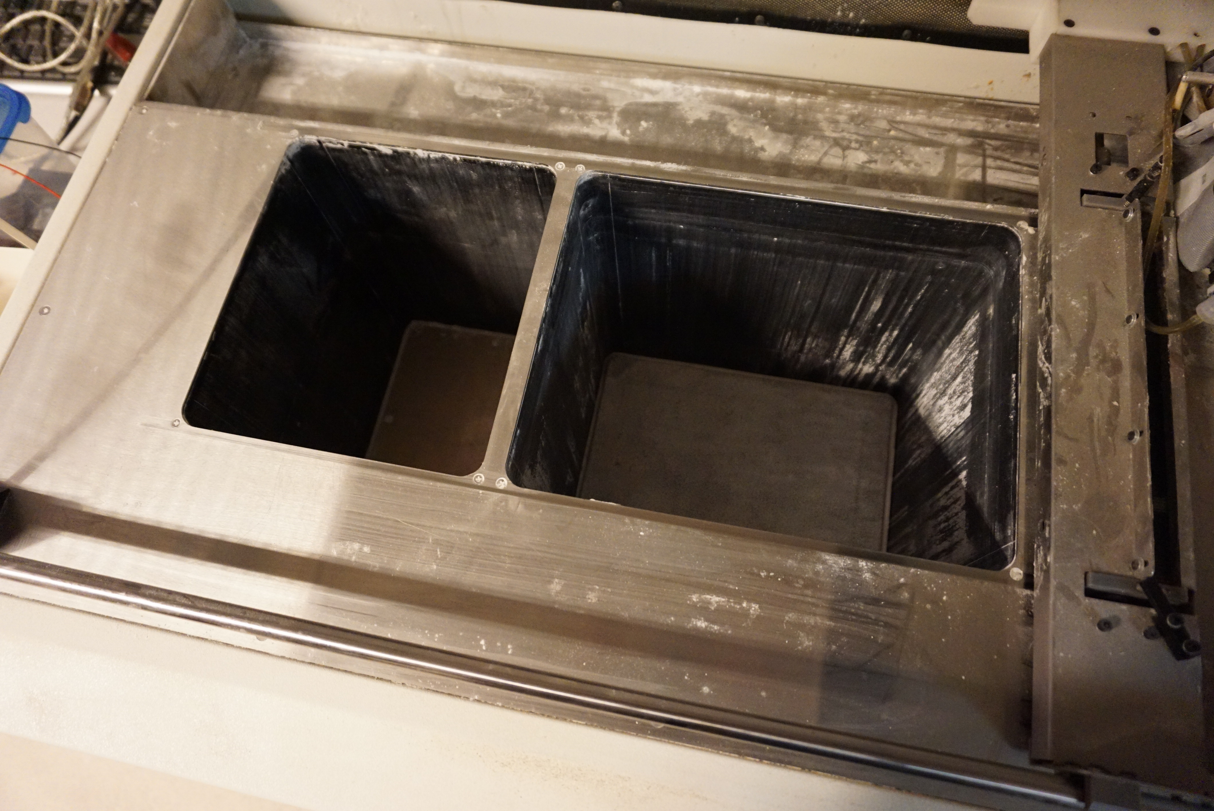
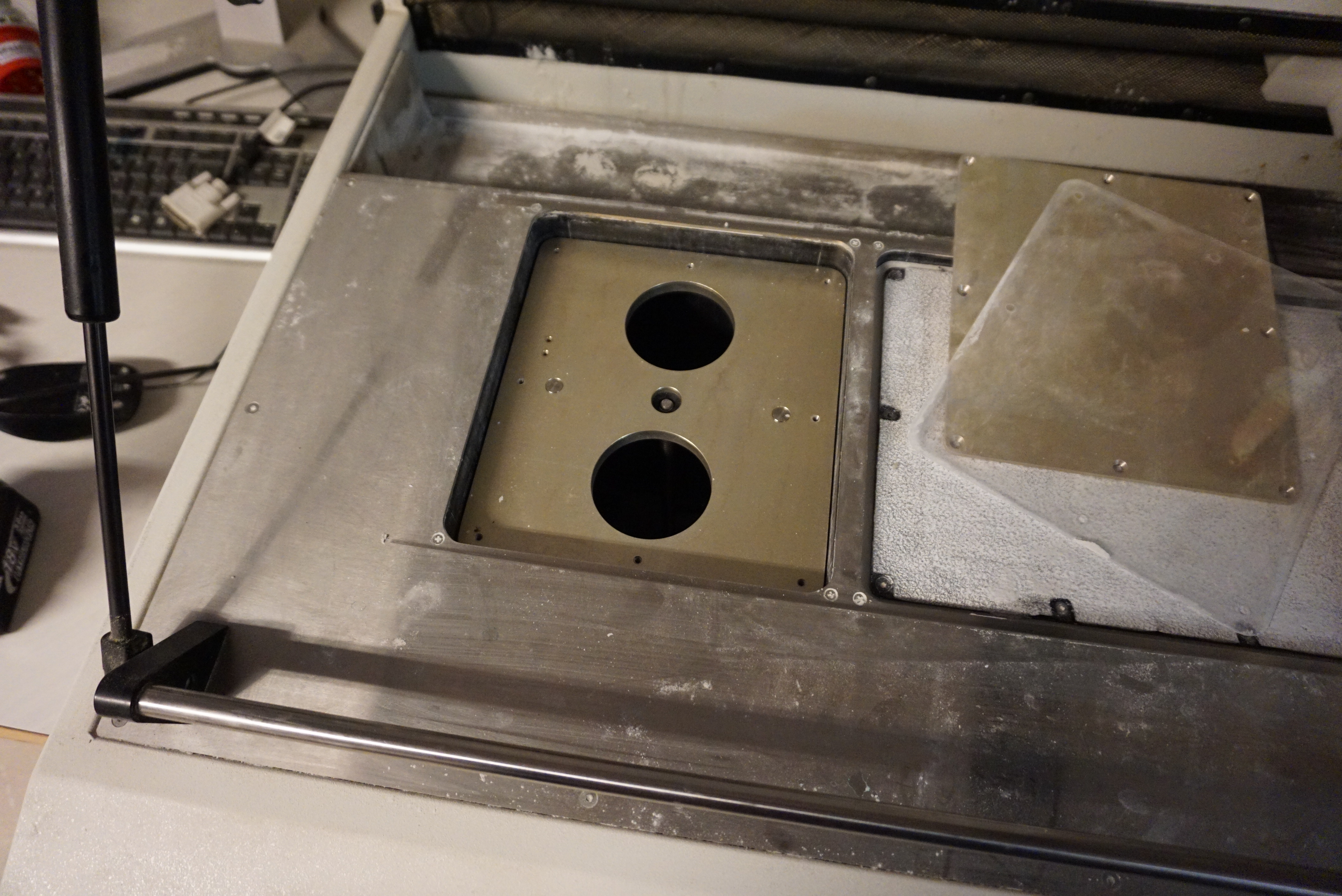
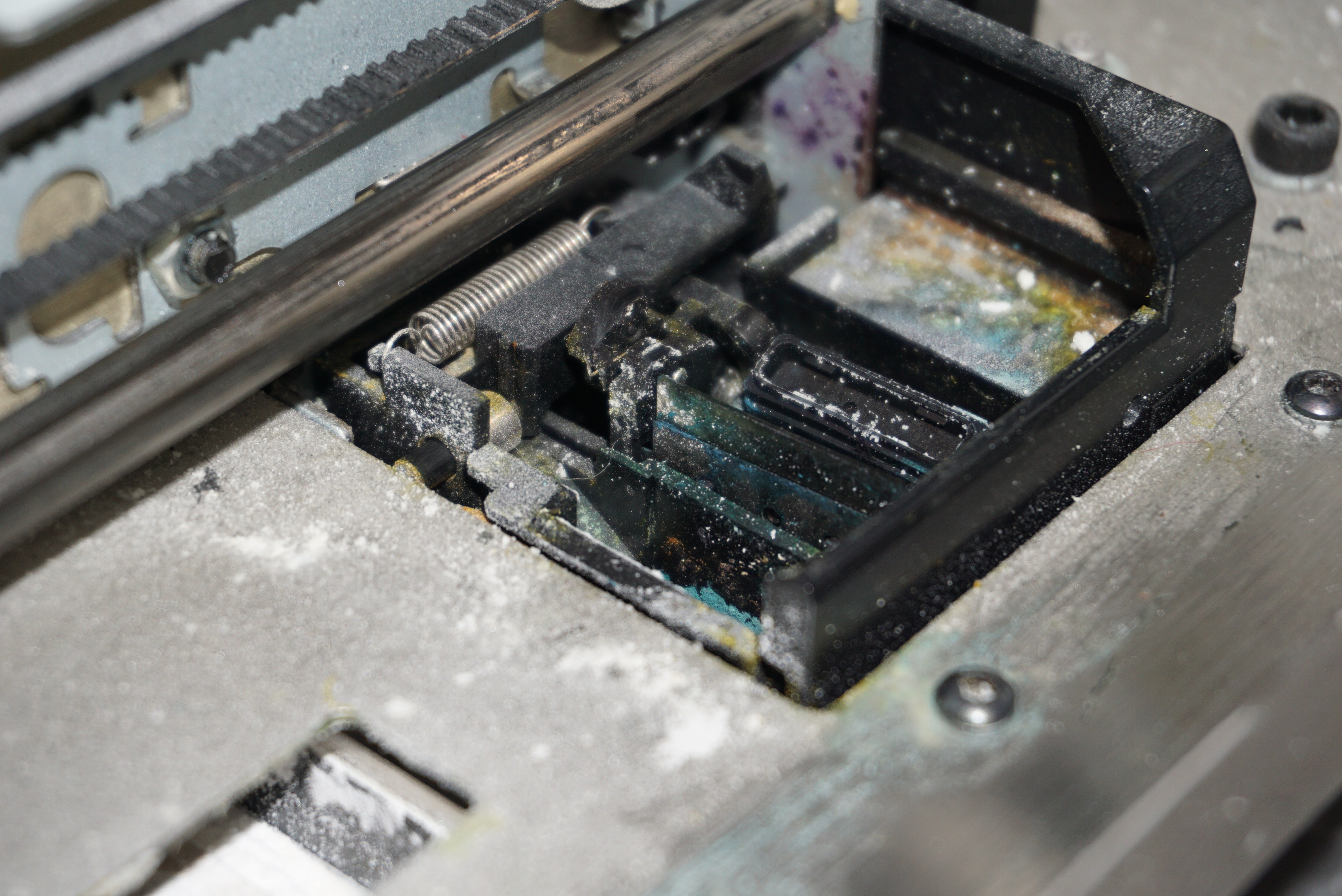
The problem with the pistons
The pistons hold the powder I will print with. Currently, these pistons wobble and have a 1-2mm gap in the edge. The seals not only prevent the powder from going past the piston, they also are 50% of the guidance of the piston. The bottom bearings do not block rotation. Obviously, printing right now would give a big mess. The piston seals needs to be fixed.
Taking them apart
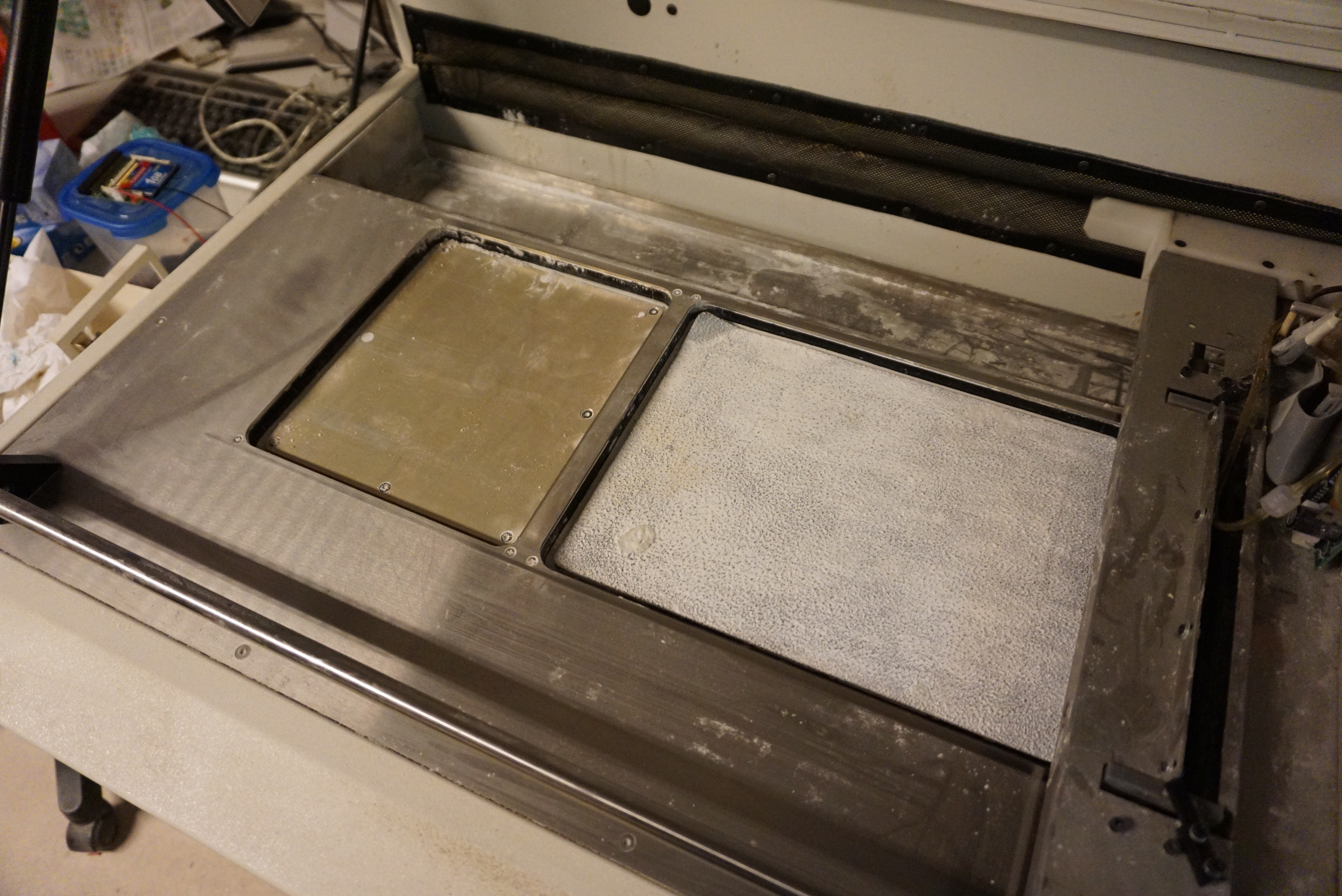
The left piston is the feed piston and the right piston is the build piston. The feed piston is pretty straight forward, with 8 screws in plain sight. The build piston has a rough rubber mat glued in place. I know from my own experience that thin layers of powder (<5mm) have a tendency to slide when a new layer is deposited, so I suspect that the mat prevents the layer from sliding. It is also very much in the way of the 10 screws holding the build piston together. I have opted to cut the rubber away where the screws are. This should not interfere with the function, and leave the screws free for when I need to do more maintenance.
The left (feed) piston and the right (build) piston before modificationThe build piston after I cut the screws free
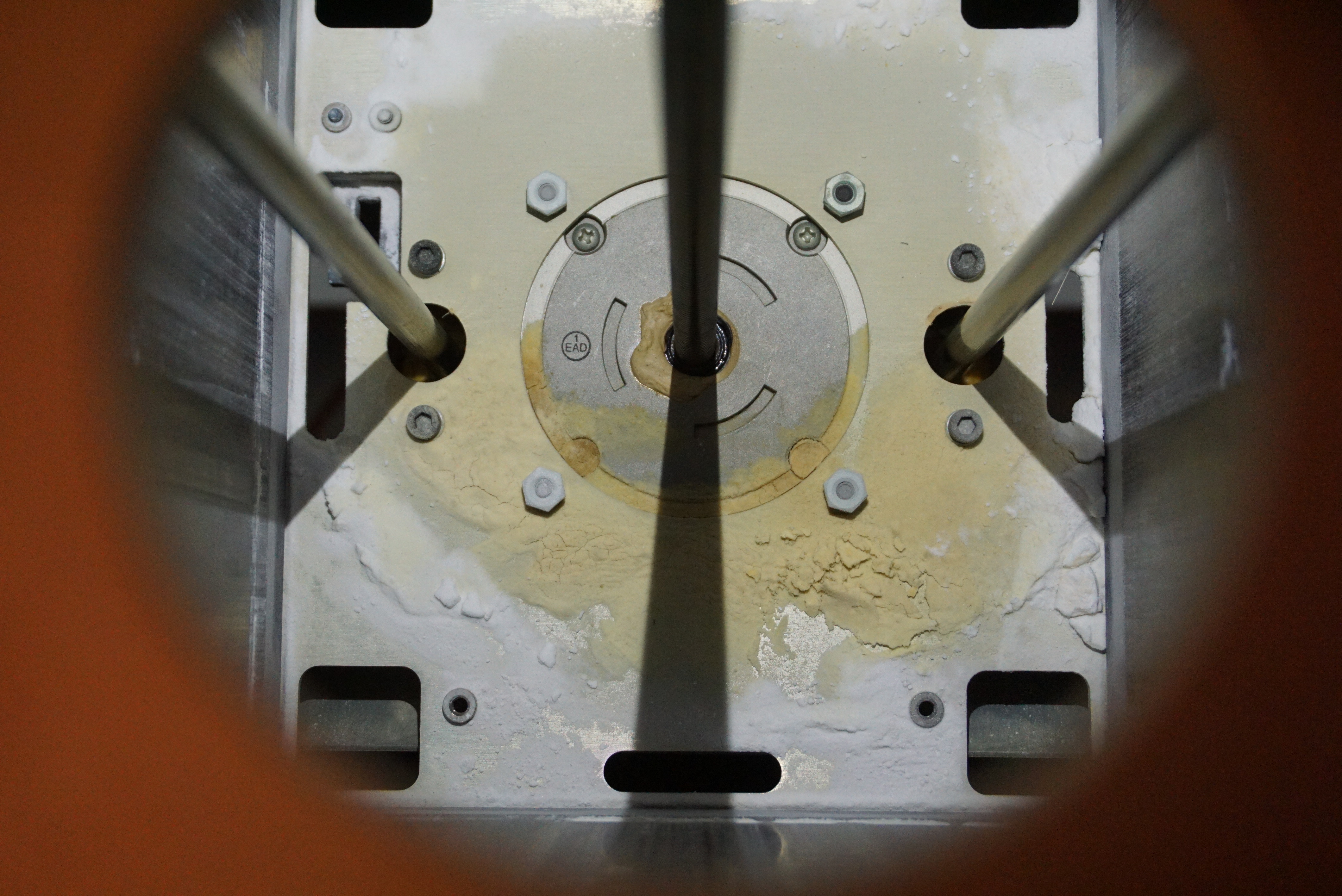
The piston is a sandwich of 4 layers. At the base is an aluminium frame that holds the guide rods and the lead screw. Then there is a soft seal, made of some sort of foam about 3mm thick (1/8″). Then a thin layer of plastic (0.1mm thick) presumably to keep the powder out of the seal. Last, there is an aluminium top plate. There are rings between the top and bottom plate to prevent the screws from compacting the seal too much.
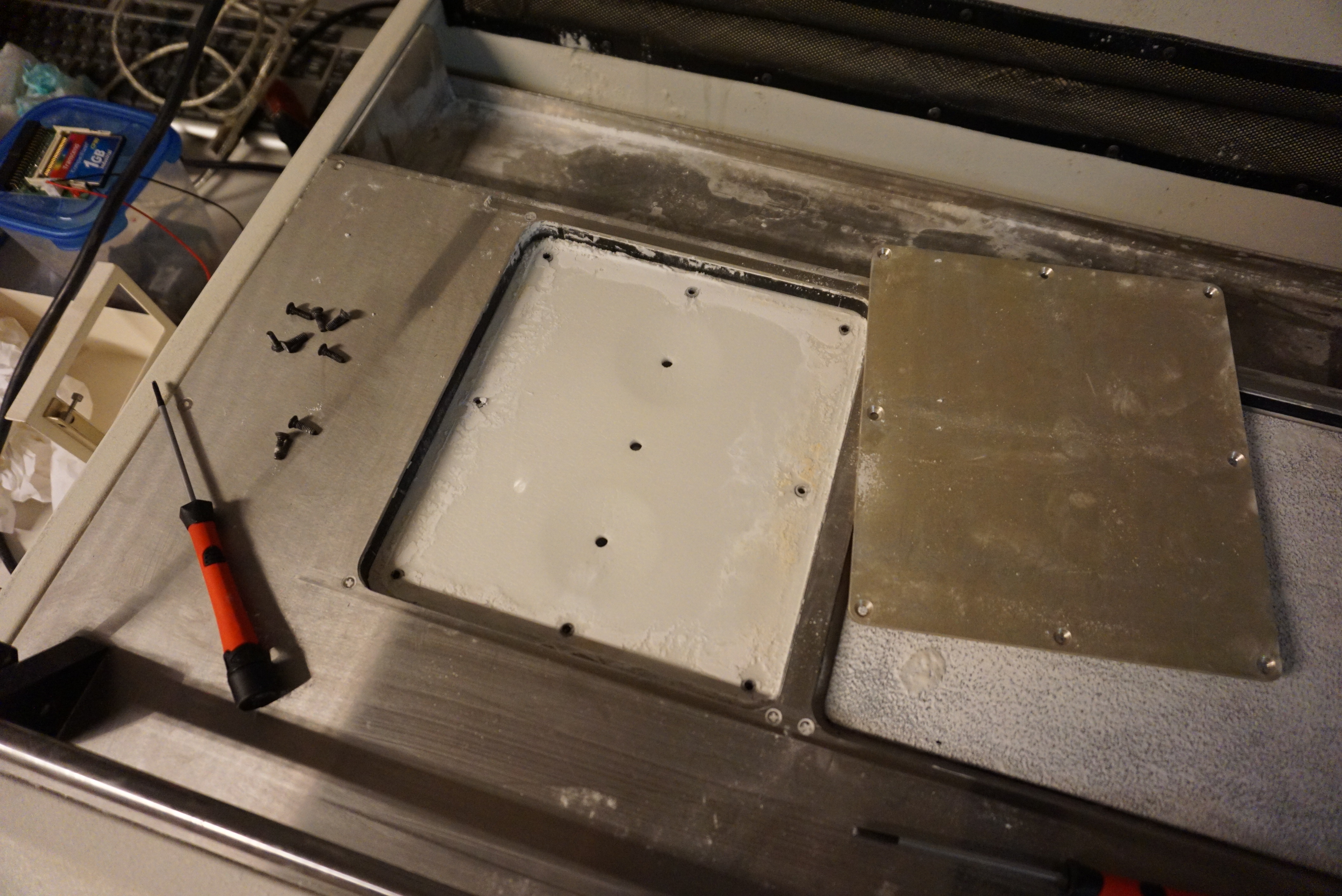
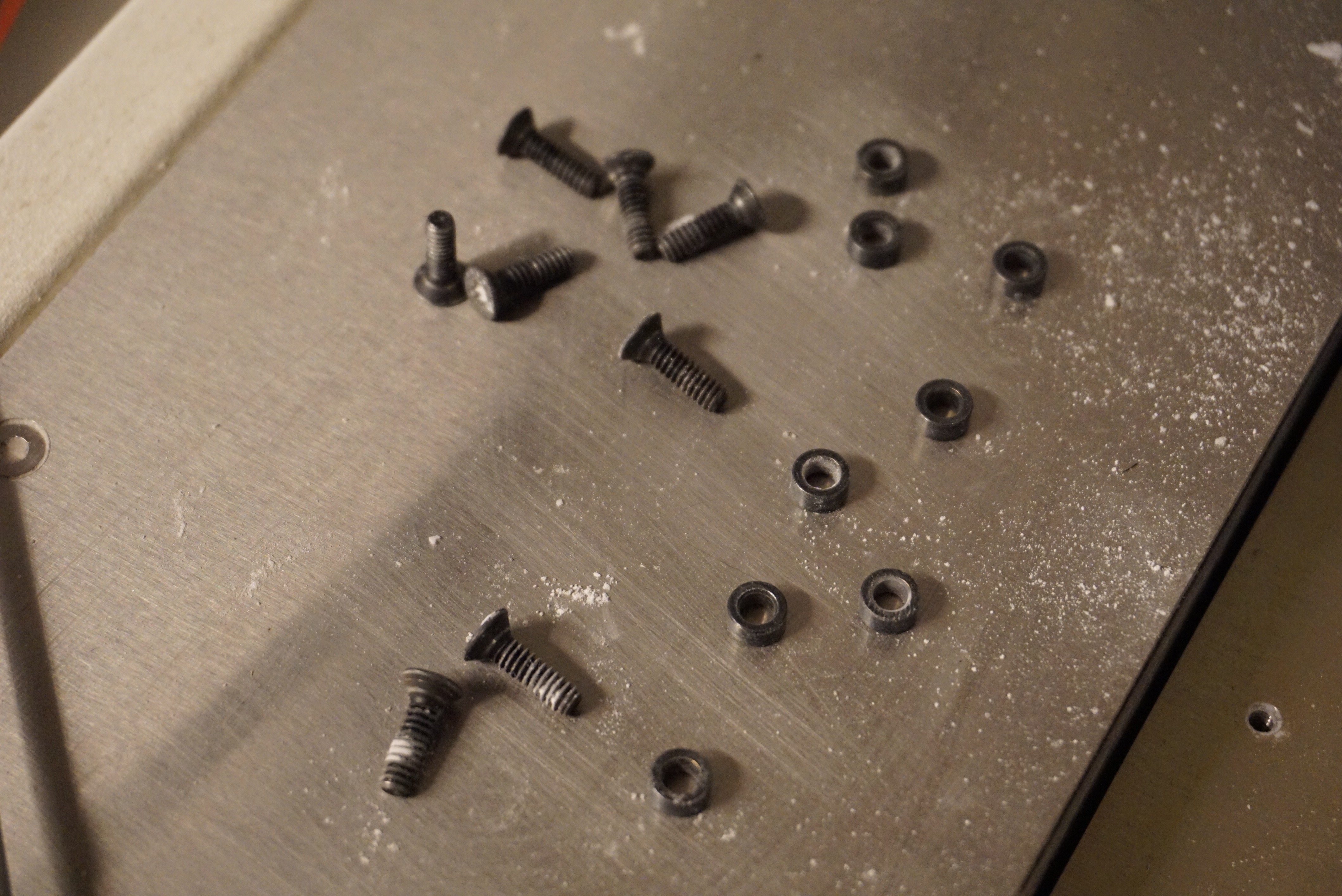
Getting to the seals
Top plate removedAll the sealsScrews and spacer ringsThe base plate of the pistonWhat’s underneath the piston
Making new seals
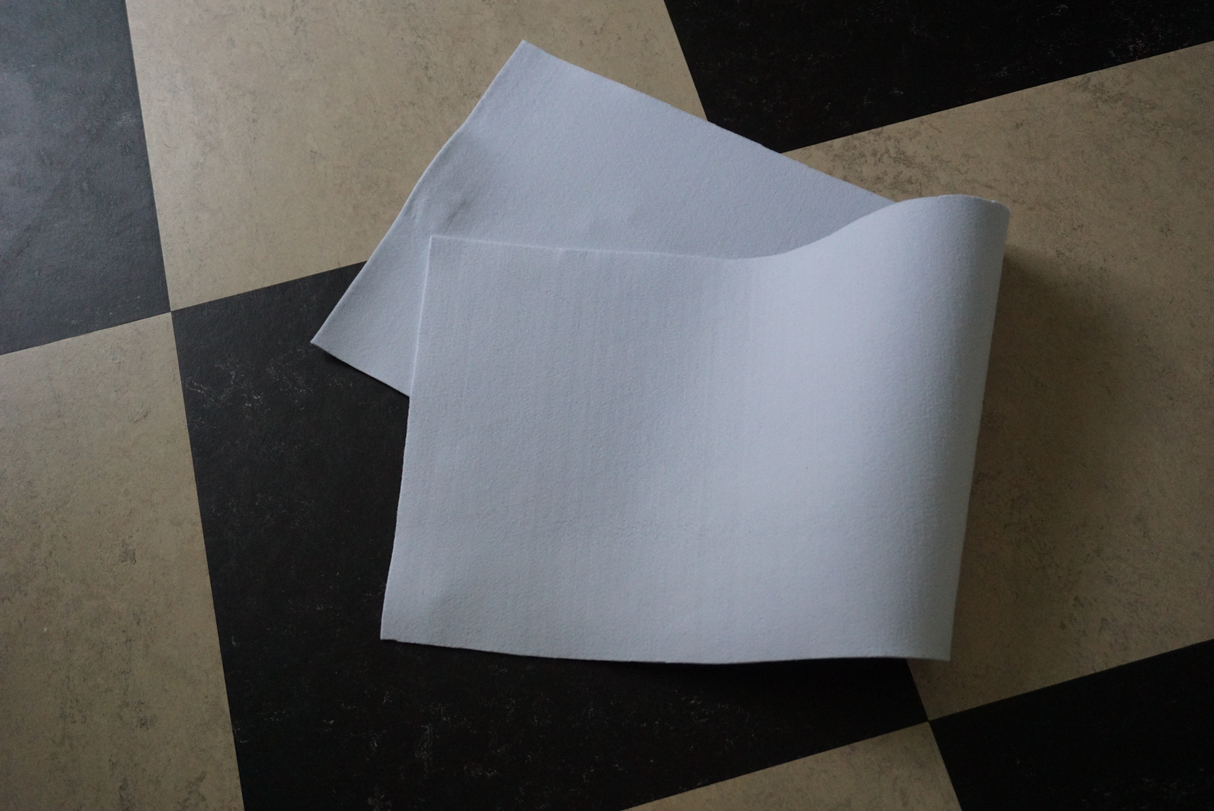
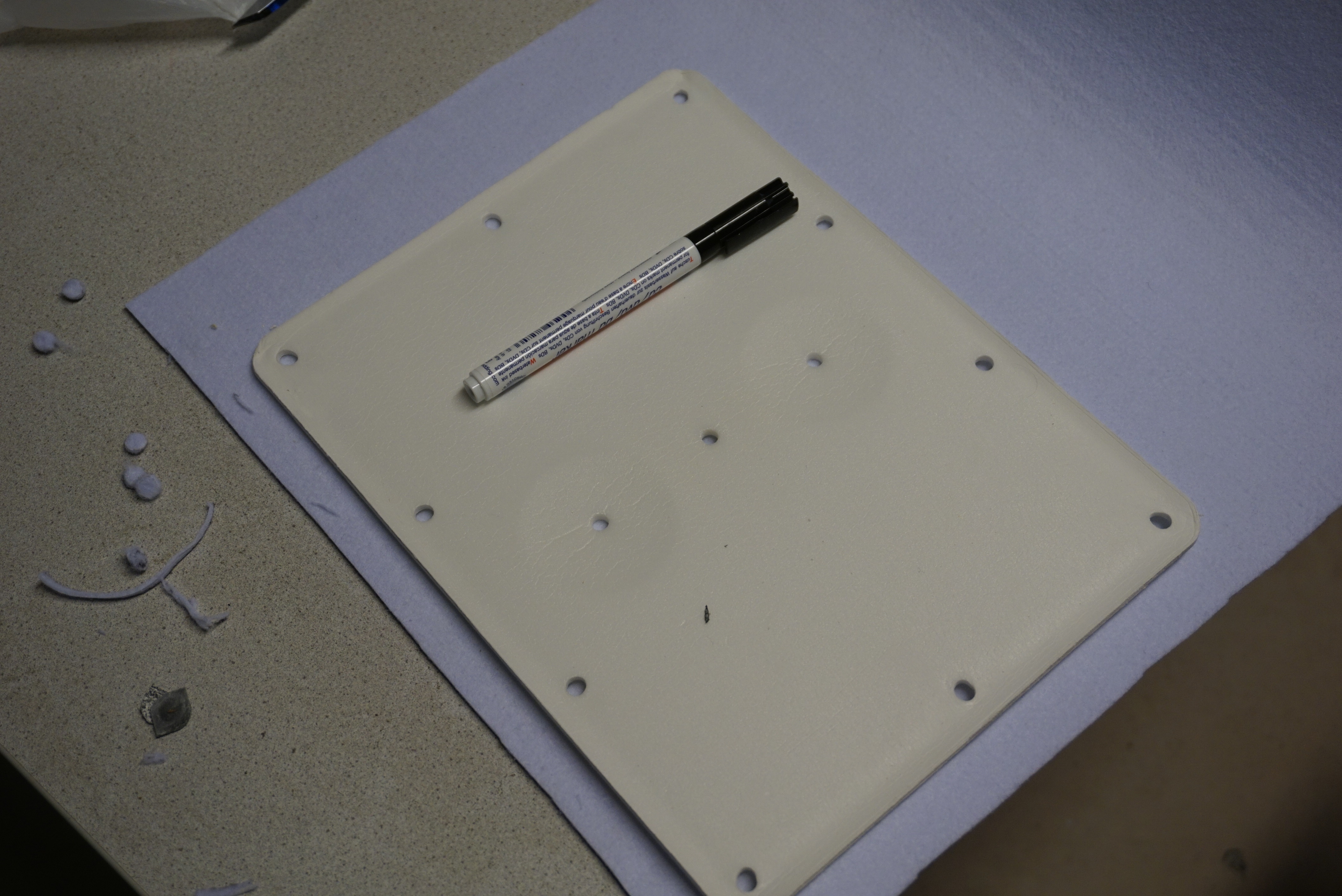
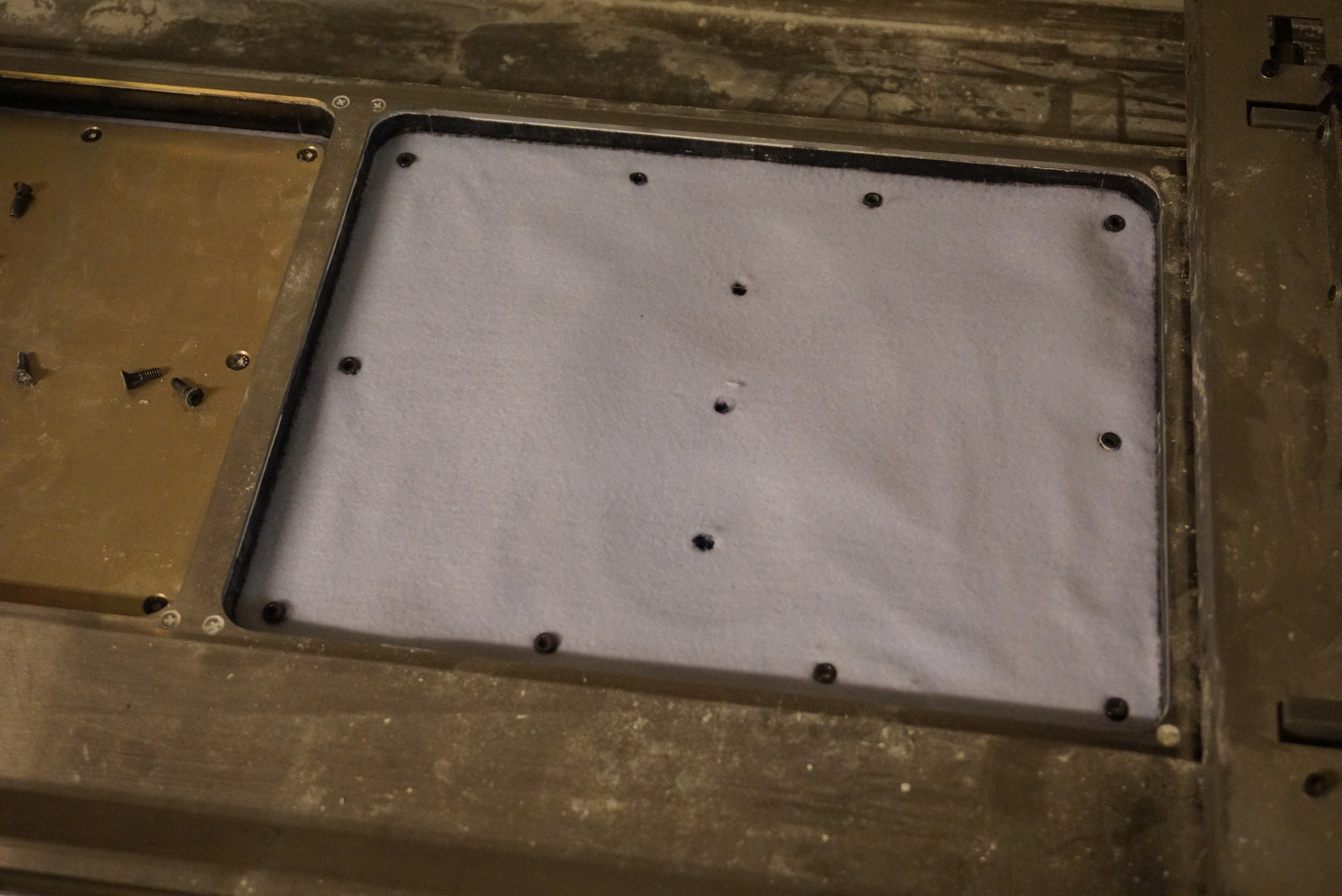
Getting the exact foam is going to be difficult. I opted to use 3mm thick felt. Felt is tough, low friction, and easy to get. The old seals were laid on top of the felt, and the contours and holes were marked with a marker. The outside contour was cut slightly oversized with a pair of scissors. The holes were punched out with an 8mm thick tube and a hammer.
3mm of felty goodness on a checkered floorMarking out the contoursReady for cuttingPunching the holes out (which was surprisingly difficult)A new sealNew seal installed
Reassembling
The new seals were put in place, the rings were placed in the holes, the old plastic was put on top of that, and the top plate was installed. I was worried that I made the felt seal too oversized, but I am happy to report it feels all right. No wobble in the piston, and no visible gap. The piston also still moves up and down, which I really appreciate.
I also took this moment to grease the piston rods and lead screw, but again, no photos of me greasing these parts.
Almost there
In the next part I will prepare a printhead so I can finally make a 3D print on the Z400. We are getting really close now.
A shorter blog today, but quite a milestone. The Z400 ejected its first ink. In the previous post I was stuck with a few options as to why the printhead was not printing. I have spent a few hours testing, and ultimately found the issue.
The first suspect was that BX-20 != BC-20. Simply slapping in a BC-20 (an original one too) resulted in the exact same result, nothing. A few attempts were made to print with the old, converted printhead, but the ink connection is not functional anymore. I did not figure out if it is to do with the CISS system. The ribbon cable was measured to check for breaks, but all signals seem to be working. I was running into dead ends.
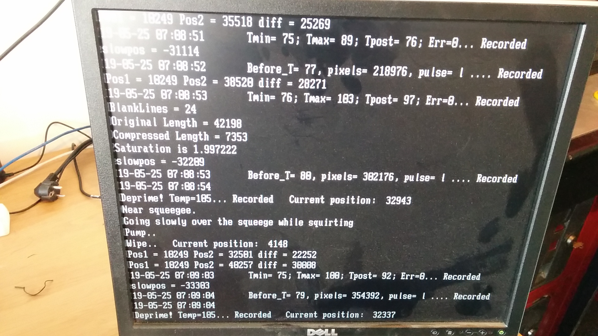
One attempt gave a critical clue. During a print, the printhead would print one sweep, then stop to flush the head with new binder (which did nothing, since we were printing with normal printheads). This would repeat every other sweep. A quick glance at the screen told us what was wrong, the head overheated, which triggered the printer to try and flush the printhead.
The Z400 was printing, but ink was not getting out of the nozzles, keeping all the heat in the head. This was also confirmed by the fact that wiping the head with a paper towel showed no ink.
“Temp=105”, that seems a big high
Armed with this knowledge, I tried applying a vacuum to the nozzles to draw ink through. We lacked the tools I needed, so I almost got a mouth full of ink, but there was now ink in the nozzles.
I loaded the started printhead in the printer, and pressed print again. Almost instantly, the printer printed a perfect image. An observation I made is that the printhead deposits an unholy amount of binder on the surface. I knew it required more than an ordinary inkjet printer, but 5 layers of ink on cardboard warped the paper. The software suggests this took over 1ml of ink (the head only holds 44ml). I now understand why CISS heads are used.
Below the obligatory video of us printing (the Tkkrlab logo seemed appropriate).
Made in the Netherlands
Now that I am actually capable of printing, the last big hurdle seems to be cleared. The printer is now capable of printing. There are still plenty of things left to do. The thing that usually starts the printhead is the dock. It has a vacuum cup to start the head. This is obviously not working, requiring me to do it myself. The pistons seem to leak, requiring me to make a new seal. I also still need CISS printheads. All things for the future.
Before getting to work, it would be nice to know if I can actually talk to the printer. It starts, sure, but can I send commands to it. The machine talks Serial (it is old), so I will need a USB to serial converter.
In comes, the PL2303, which is in this store bought USB to serial converter I have had for a over a decade. Also, it does not work, giving me the yellow triangle of complaining. Store bought converter is a fake, and it will need a hack. Luckily, it exists.
I also need to put the serial port on COM1-4, else the software doesn’t want to talk to it. Yay old machines. The good news, the machine talks back. I can toggle some of the hardware, and I can get information back.
Greasing the works
Before doing anything serious I thought it was wise to give all the motion a check, and if it needs it, some oil or grease. Standing still is generally not good for machines. The belts seem absolutely fine. Still at a decent amount of tension, and no odd cracks.
Perfectly adequate beltThe snow plows are the rectangular block on either side of the piston
With the manual in hand, I went and greased the fast axis and oiled the snow plow. The ‘snow plows’ are plain bearing blocks that slide on either side of the piston, on the actual top surface. They need to be oiled before every print. Greasing the slow axis shaft was something that I was not allowed to do according to the manual :(, but I did it anyway. It has a grease port, but the bearings have no proper wipers, so I just greased the shaft itself. Pistons will be for a future post, first I want to see ink.
Also, not many photo’s. A greased axle looks the same as a dry one.
Binder lines
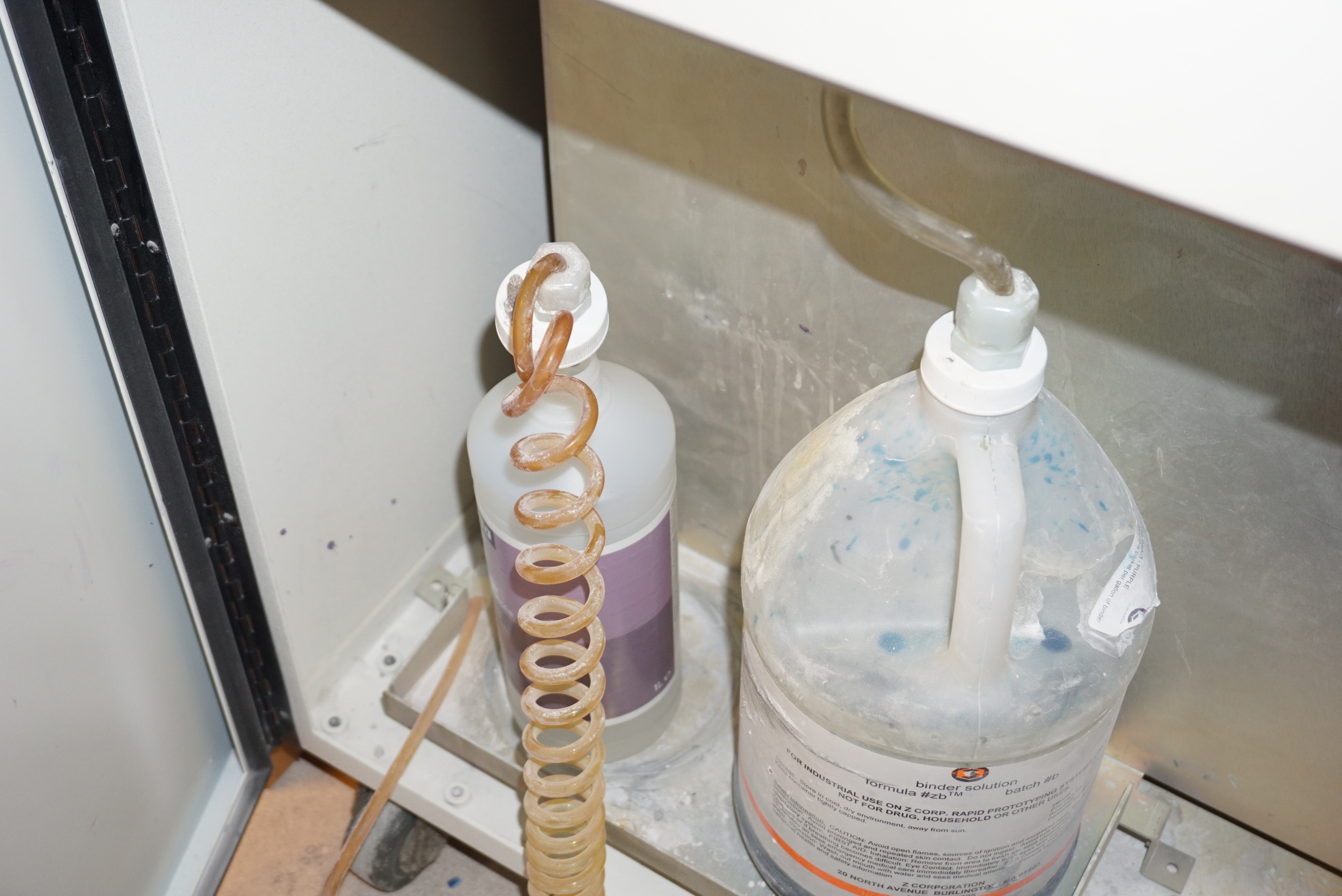
The current bottle of binder is this odd blue color. I have no idea if this is still usable, but it is in the binder lines, and I do not want it there. The manual states flushing the lines with demineralized water if the machine will not print for extended amounts of time. This is what I will do. The software has a nice function that allows you to flush the lines. Simply add a bottle of water at the input, and then hold the ‘Feed up’ button until you are done flushing. ‘This may take 5 minutes’.
Left, water. Right, waste bottleNice and clean again
Wait, 5 minutes, while holding the button, a dinky dome cap button, the whole time!? Yes, the machine does not flush for 5 minutes, it flushes until you release the button. While I am happy that it lets you chose how long to flush, you stand there for 5 minutes holding a crappy button.
Also consider this thought. The binder (and powder) that this machine uses is ludicrously expensive. Current estimate is €100-500. Holding the button for 5 minutes cost around 100-200ml of binder. This is at least €10, at the most €100 in binder, just flushed out of the system. Running this machine was not cheap. Now I am not going to be using original materials, but still.
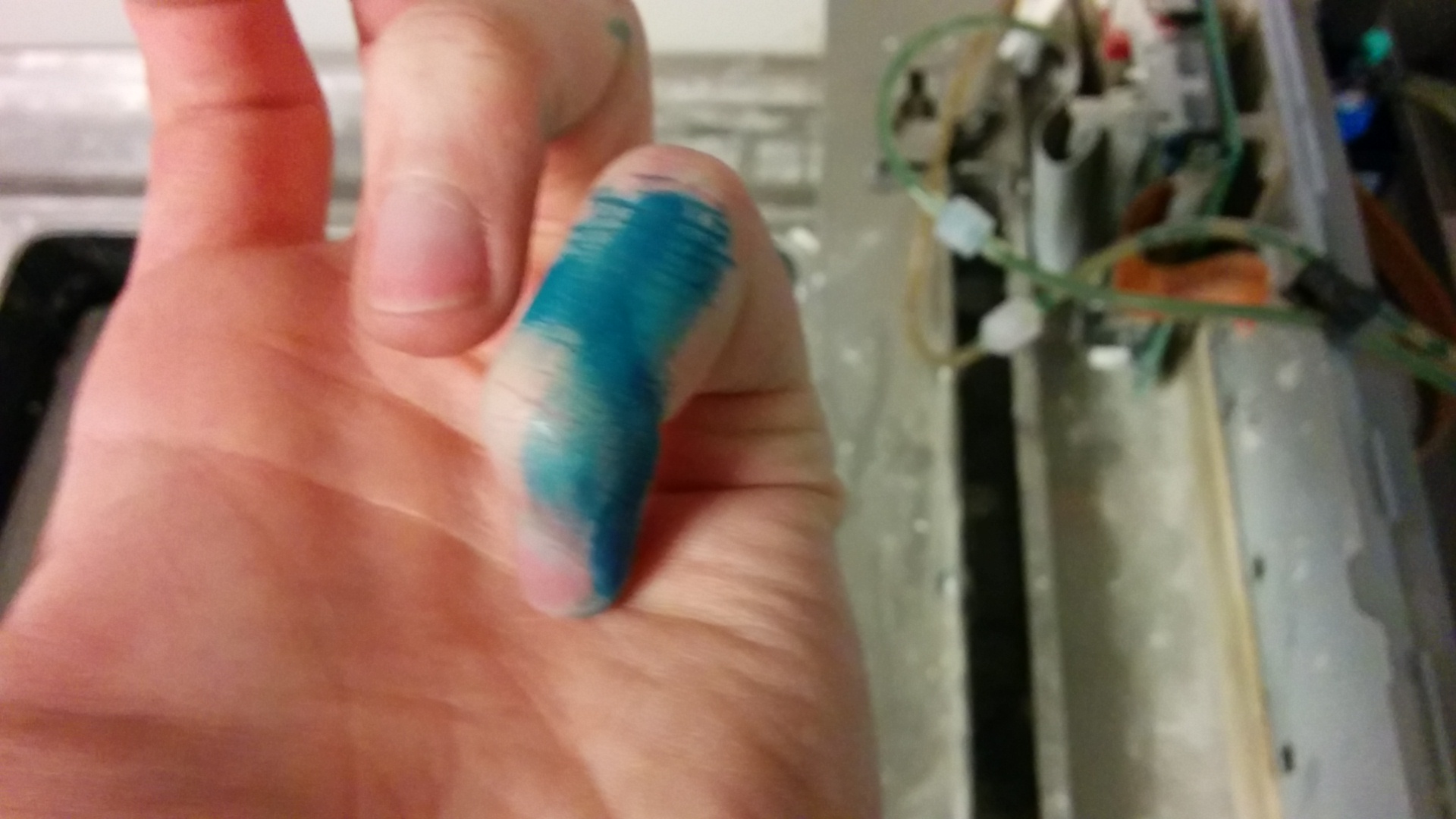
Also, while reconnecting some things during the flushing, I got some of the binder on my hand. I am happy to report that I am now 1% smurf, this stuff does not come off.
Obligatory Eiffel 65 lyrics
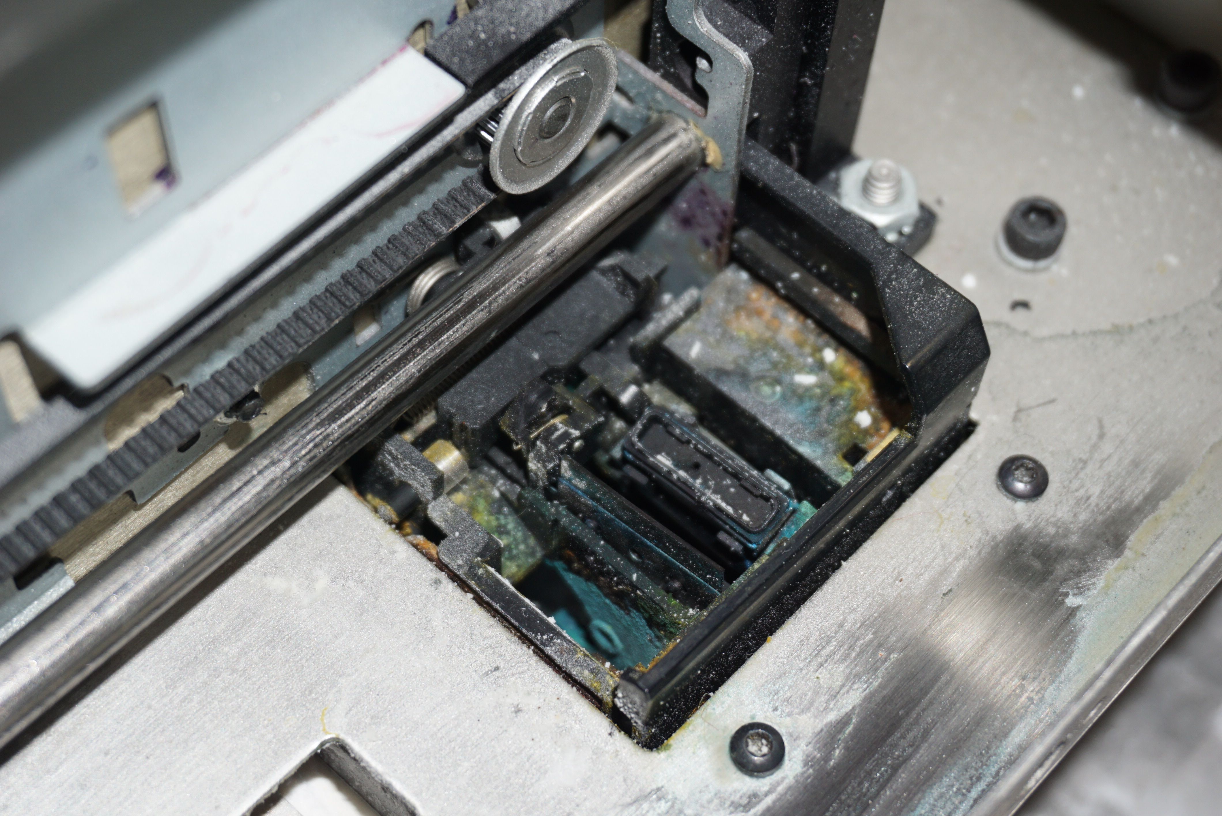
Printhead dock
The dock is where the printhead spends most of it’s time. It consists of a squeegee (I really like that word) and a suction/capping port. All is made of rubber, and though it has been sitting still for a while, it does still feel decent. I cannot really see if it makes proper contact, since the printhead obscures it most of the time, but for sake of argument, lets assume it works.
Surprisingly clean for something in a powder printerSqueegee intact
Printhead
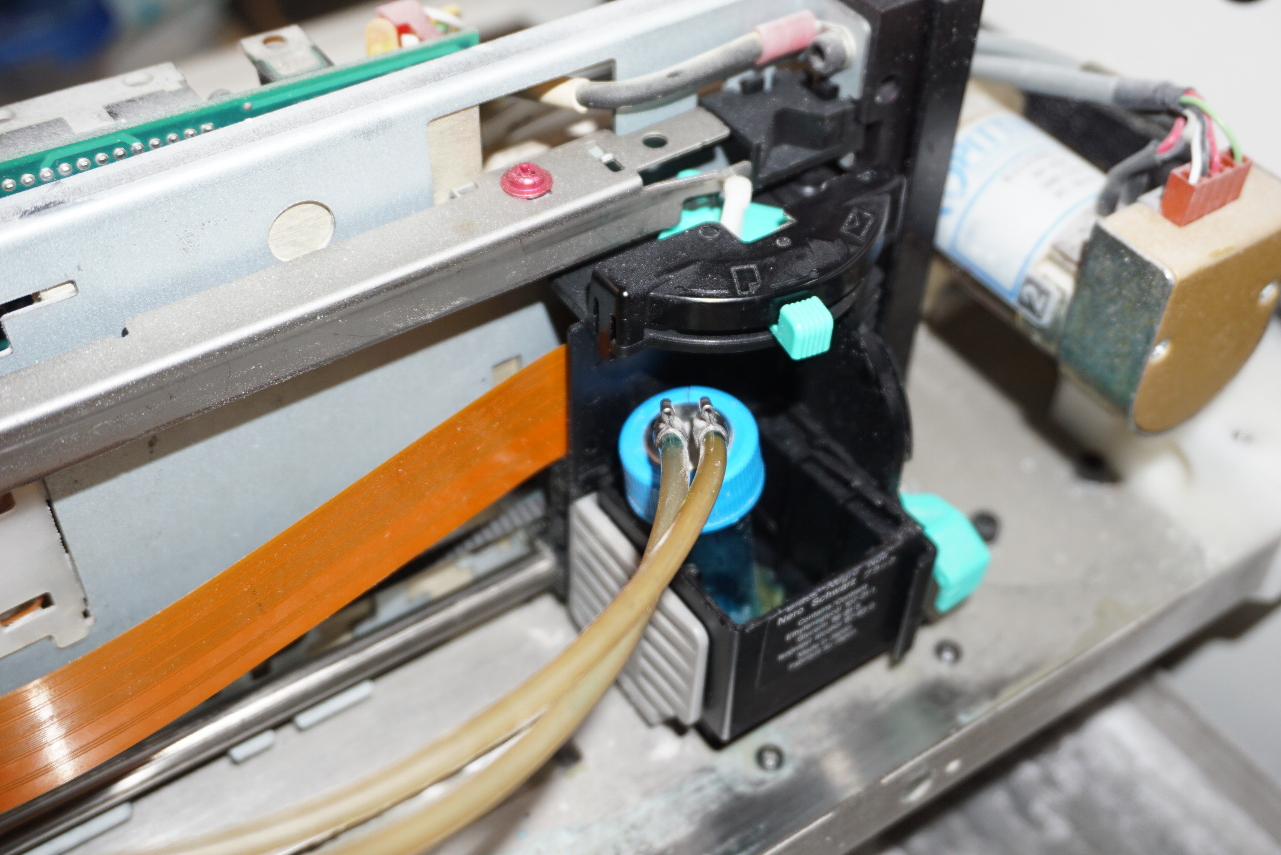
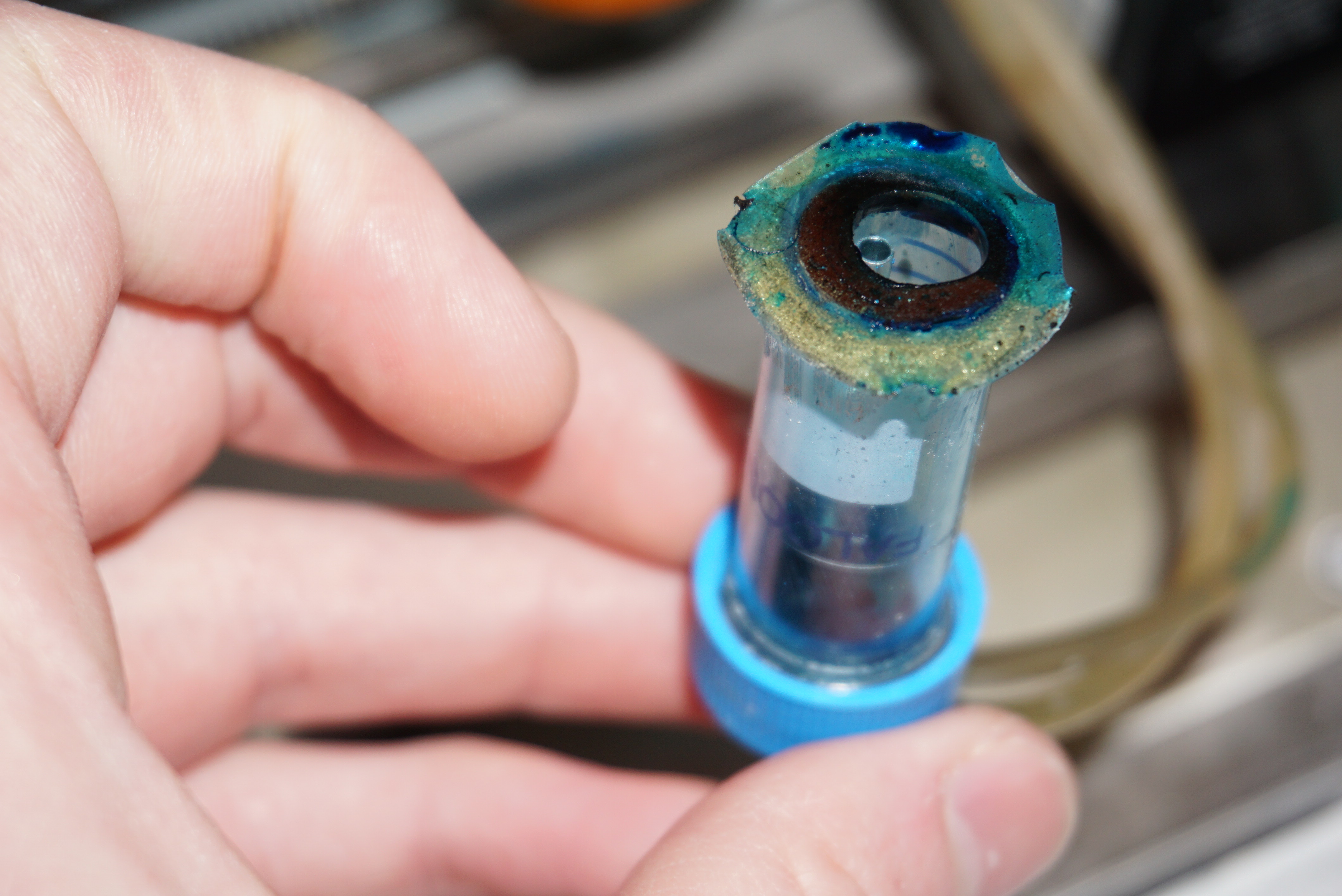
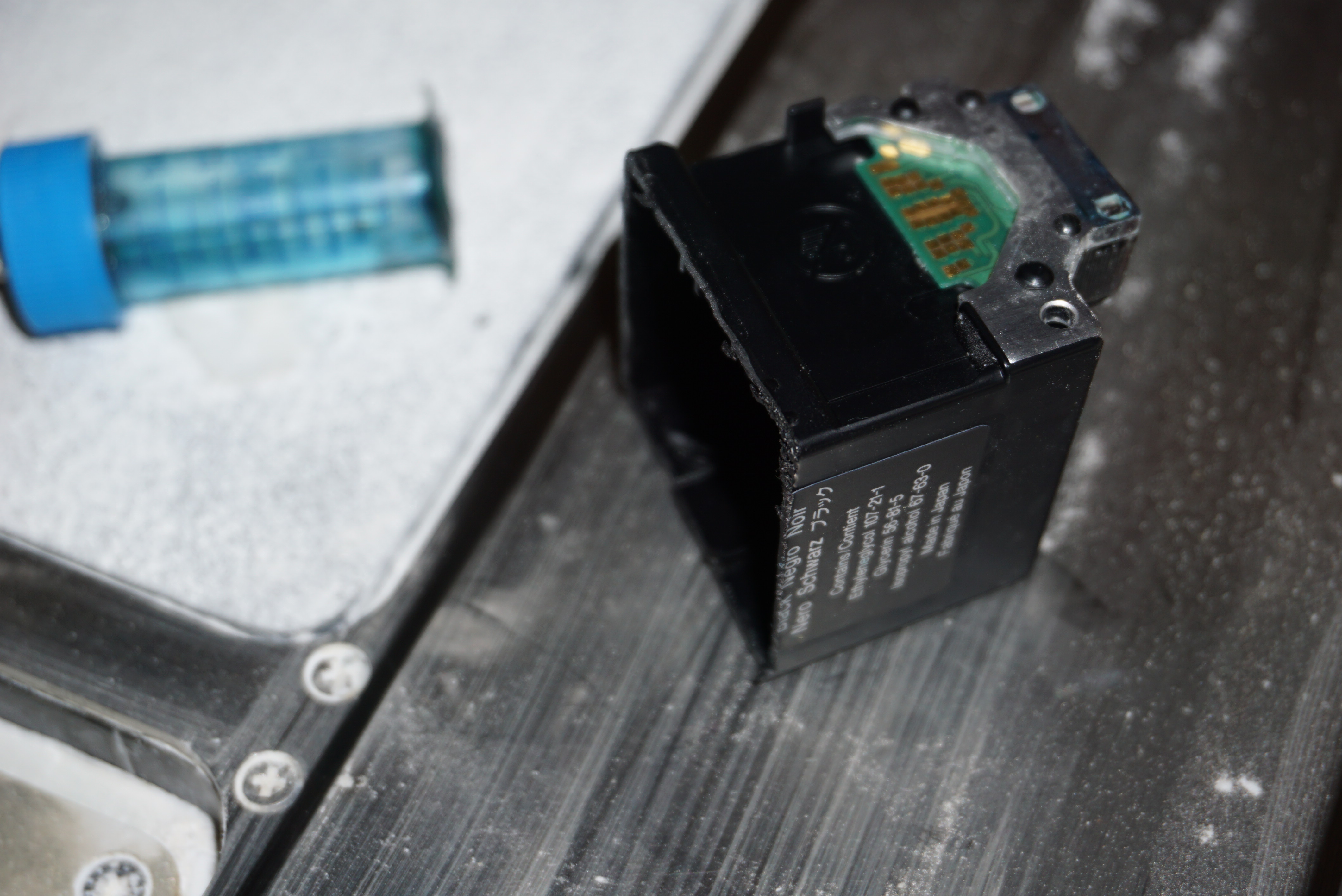
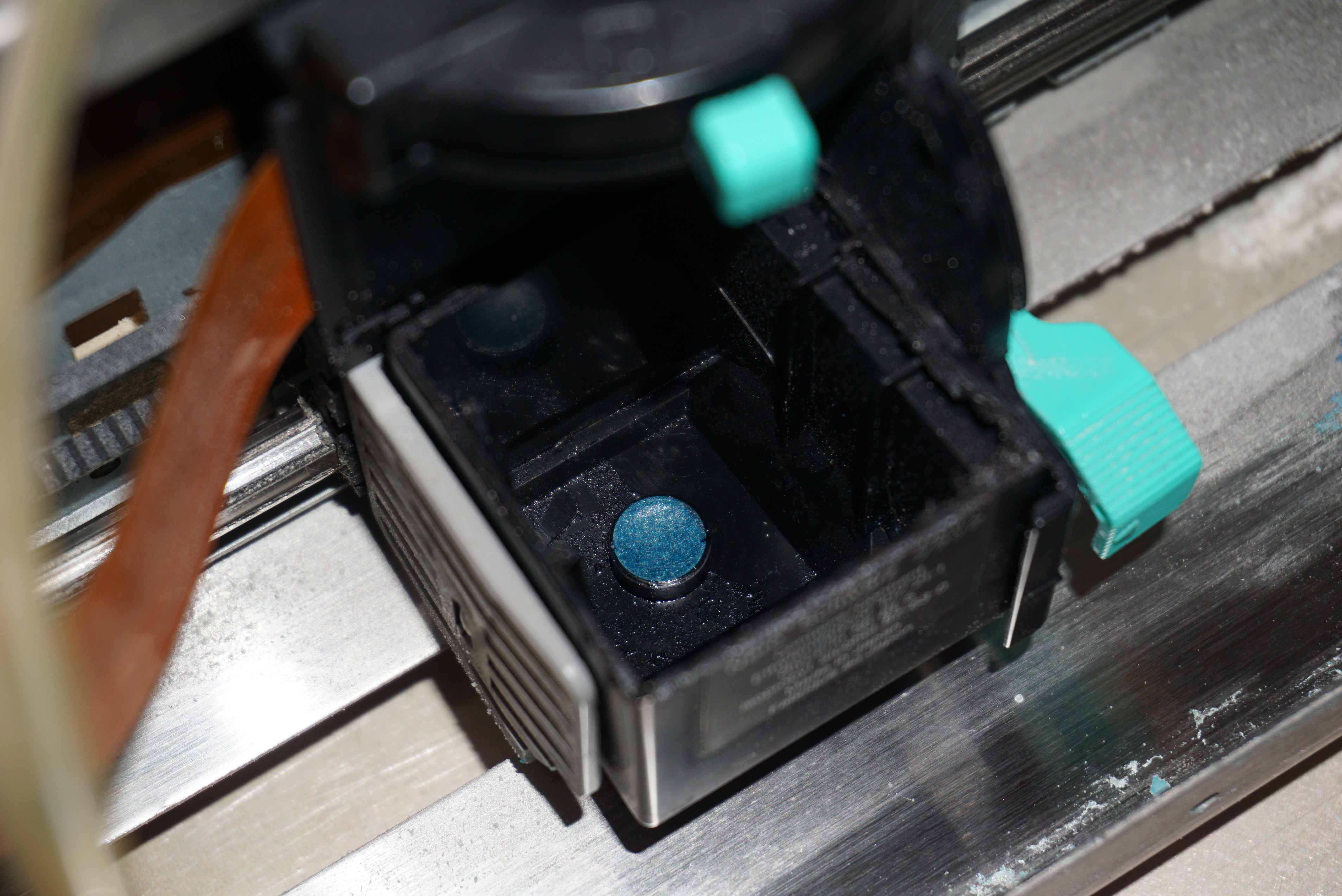
The final piece of the puzzle for today is the printhead connector. The Z400 uses a CISS (continuous Ink Supply System) printhead, and the BC-20 is definitely not a CISS printhead. It was cut open by Zcorp and a special adapter was added to the printhead. A special connector is used to make contact with the printhead. This connector is a medical plastic container of some sort.
Connector somewhat in placeRubber seal2 Tubes at different heightsThat is a cut open printhead all rightThe inside of a printhead
There are several ways of making a BC-20 a zcorp head. There is simply gluing on hose glands to the printhead, Cutting the top of the printhead of and gluing a in special adapter (no link). There is also what my Z400 has, which is an odd hack, but a seemingly functional one.
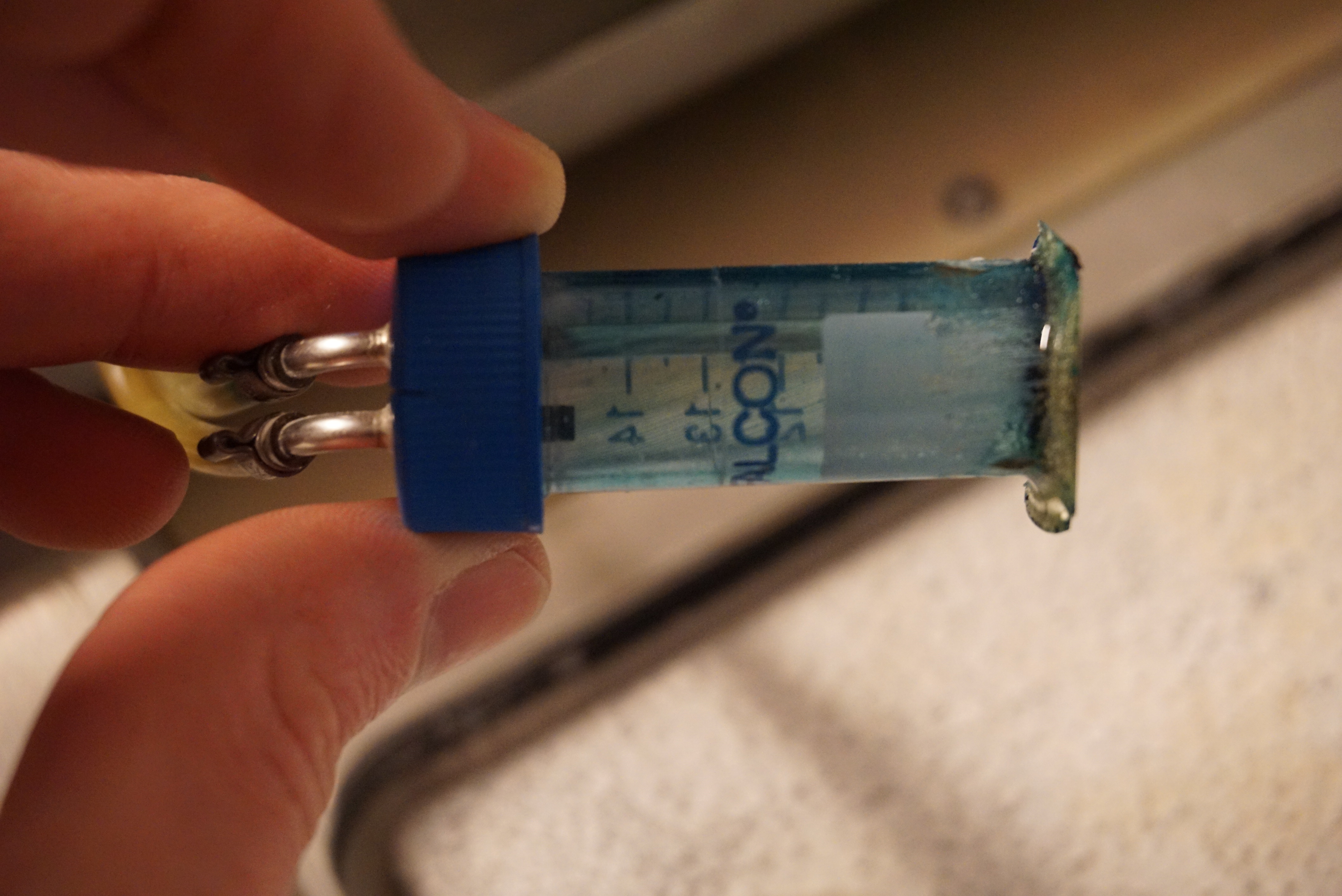
The connector seems to be the original one, but it has an extra rubber gasket glued to it that interfaces with a boss that is naturally in the printhead. It is a bit weaker of a connection, but it takes much less work to modify the printhead itself. The printhead only needs to be cut open. I will see if I can make this system work.
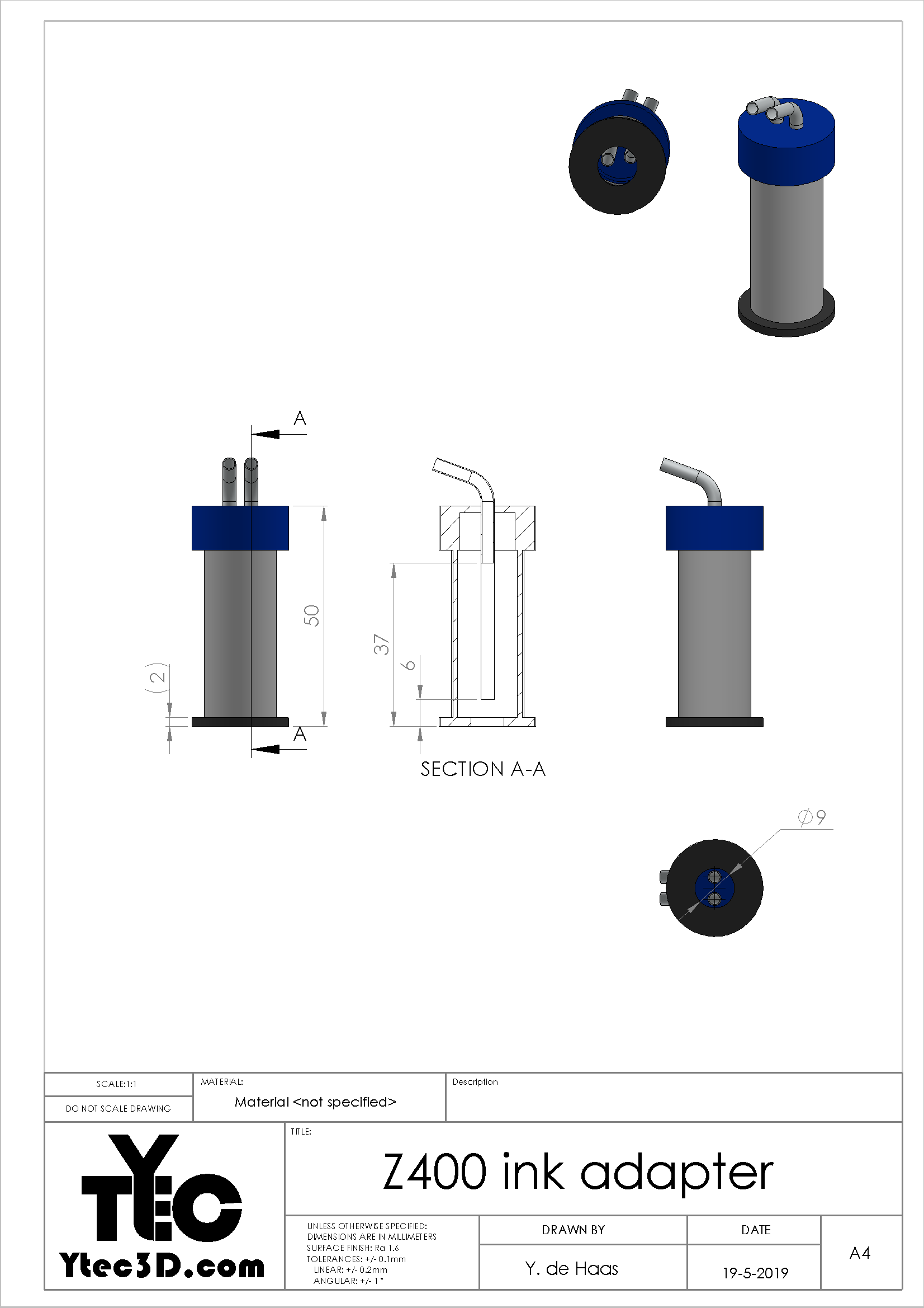
I did some measurements of the connector, and the drawing is below.
Ejecting ink
Enough talk, lets test it. Does the Z400 actually print?
Yes, but not really. It moves and tries to print, but no ink actually comes out. It is convinced it works, the printhead is sensed. When I pull out the printhead on a life machine, it gives all sorts of errors (suggesting it sees something). Somehow, ink is not flowing. A few possible options:
The dock does not start the printhead properly;
The printhead freezes too quickly after it was primed;
Though the printhead is sensed, no full connection to the head is made;
The machine is so altered that it only prints with modified printheads;
The printhead I have is a dud (It is a BX-20, though I am told they are the same)
I do not know which issue it is right now, but I will start ruling out the possibilities as soon as possible.
The last time I checked the HDD and all power supplies. Everything seemed fine. I then added a transformer to run the printer on the 115V it wants. When we wanted to power the printer, all we got was lights, but no sign of any life from the computer.
Powering the PC (again)
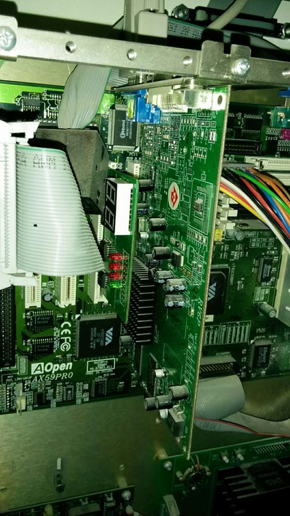
The first task was to see if the motherboard was giving post codes when the printer was being powered. We never heard any beeps, but there might simply not be a buzzer on the motherboard. Getting post codes might give an indication of what is actually missing or wrong on the motherboard. We can then fix these issues and hopefully the printer will boot properly. Armed with a PCI post card, we went back to the printer
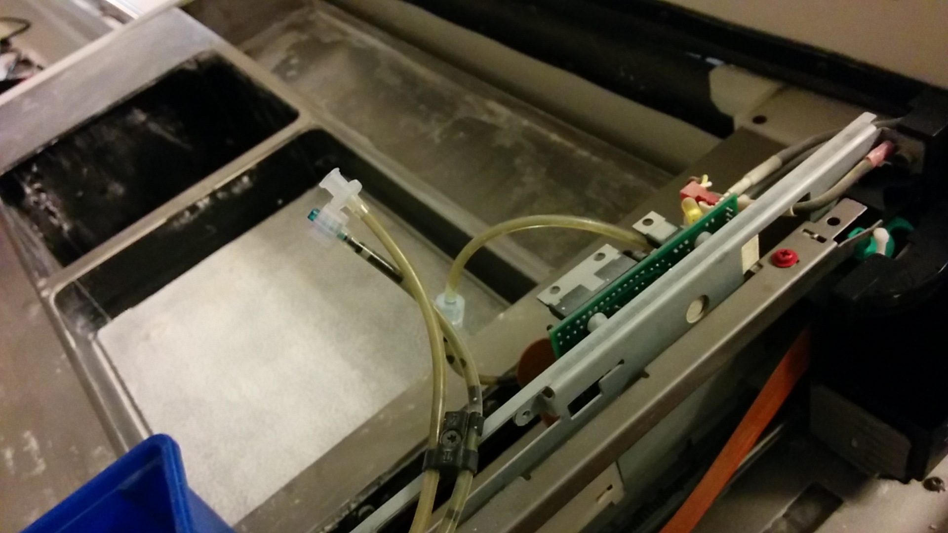
We plugged the card in an empty PCI port and powered the machine. The card did light up bug gave no post codes, only some leds and two dots. We then suddenly heard noise. The clicking of a heavy solenoid that turned out to be the binder pump. Then the printer trying to home and running into random parts we still had in the build area.
There seemed to be life there. We plugged the PCI post board in another PCI port. We cleared the junk from the build area and tried again. More pumping, homing of all axes and an obnoxious alarm that is a strong contestant for ‘parts that will get bypassed in the future’. It is also at this point we realized that the fluid line was about to pump into open air. We did manage to turn the printer off before there was too much of a mess, but there is now blue ink in one of the corners. The binder line was connected to itself to complete the loop, so the machine would be able to operate as if there was a printhead.
What did I actually do that made the printer work where before it didn’t? What magical combination of actions did I do to make everything start?
I have no clue, but it is working for now. I will keep my eyes open for any odd behavior that might cause the machine to stop working. Computers that magically start working where they did not before are incredibly suspicious, but they are better than computers that are presumed dead and not revivable.
Boot cycle
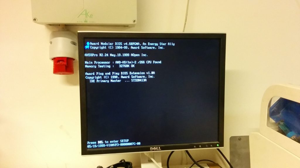
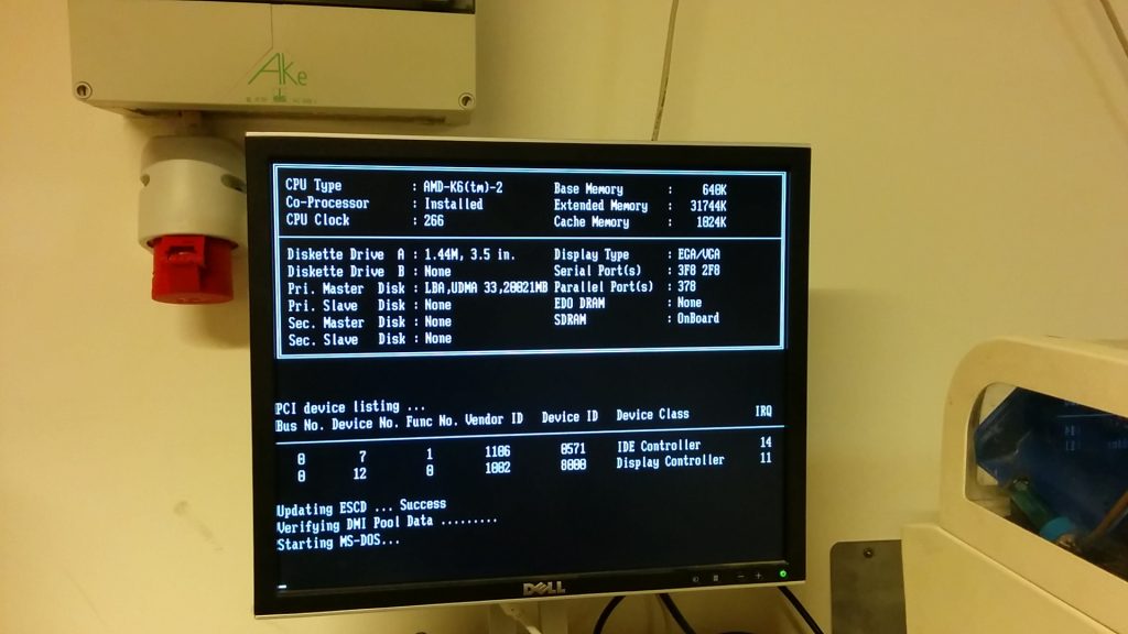
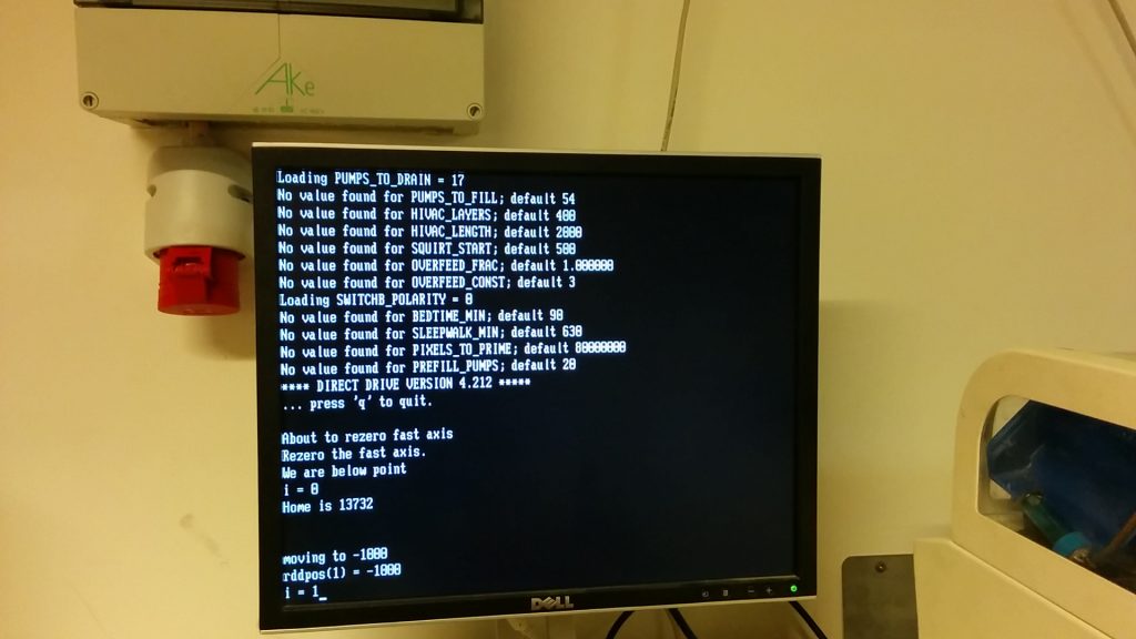
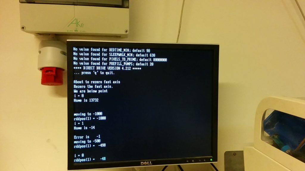
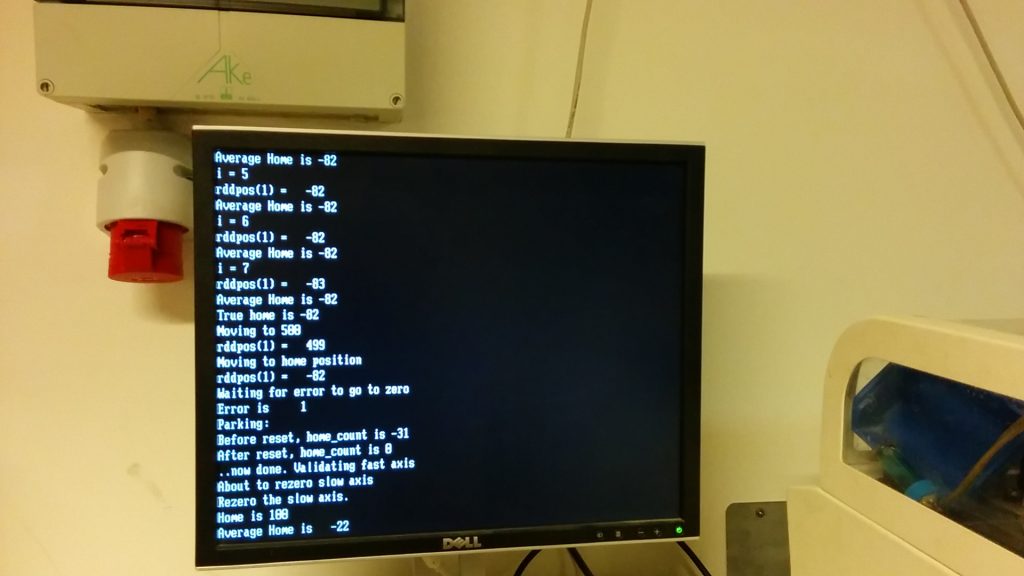
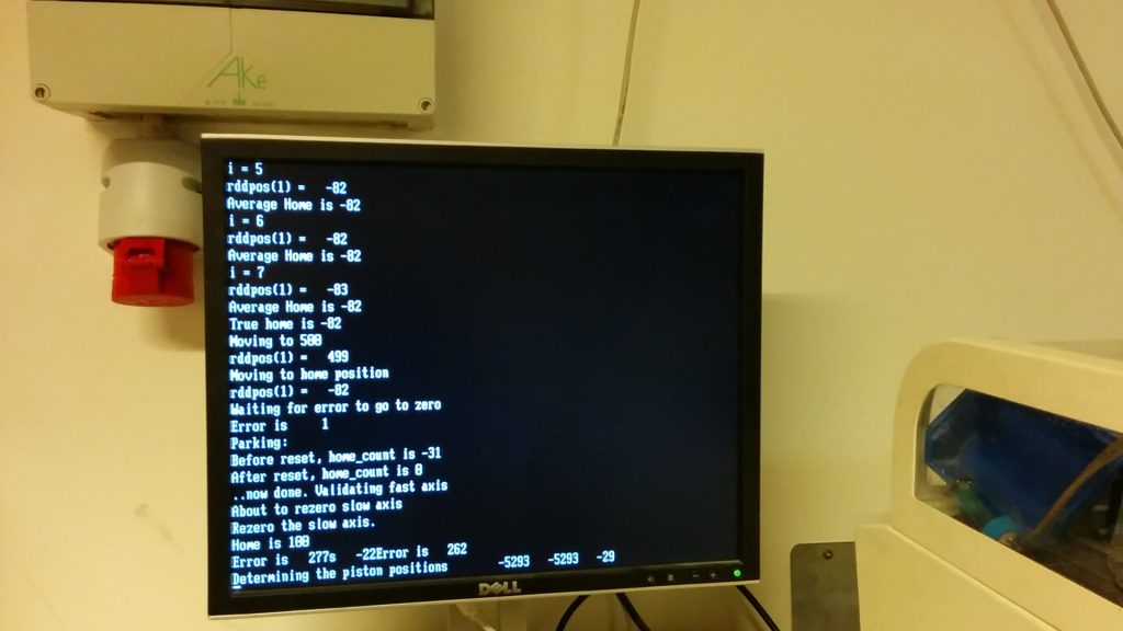
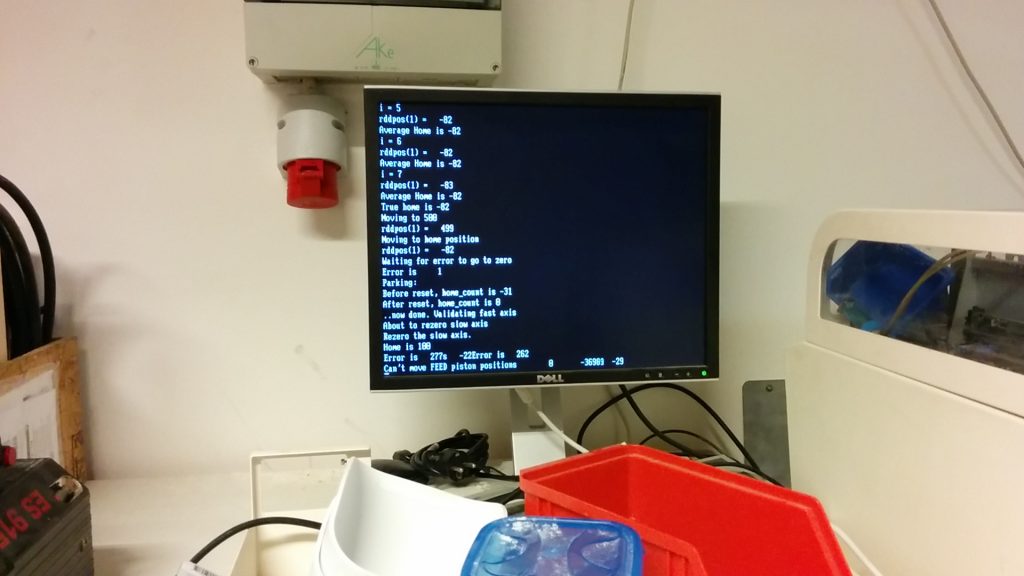
We added a screen. The Z400 has the option of having a screen and PS2 keyboard to debug the PC of the printer itself. I was very curious what the printer was actually doing. As it turns out it writes literally everything that it is doing to this screen. Below photo’s of the screens we saw.
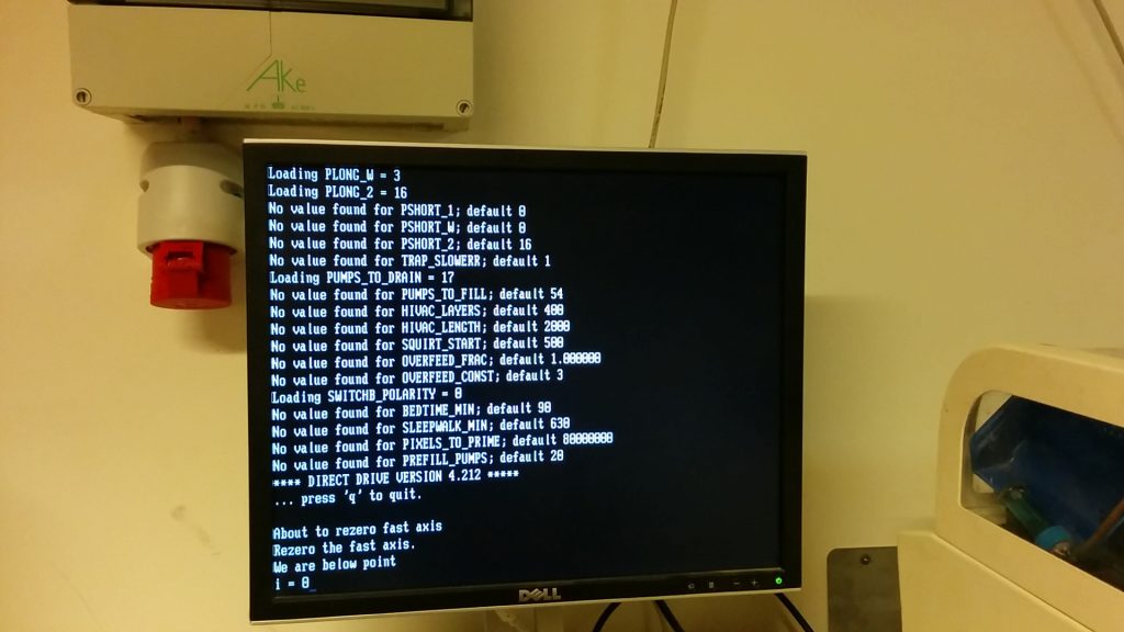
What happens during the startup of the printer
Binder is pumped around until it reaches sensors;
The fast and slow axis are homed. The printer wiggles both around a dozen or so times to get an exact position;
The pistons move all the way down to sensors and then up to their old position (an idea which I like very much);
The printhead is tested and parked.
Roadmap
Now that the PC seems to be working and all systems can be tested, there is a whole list of items that need to be done.
See if I can get the software to work: So far I have only had the machine operate standalone.
Clean ink lines: I had the old, weird ink running through them in a test, clean this with demineralized water and IPA.
Check timing belts: They seem fine but the machine is getting older;
Grease/oil axes/screws: The printer has been gathering dust for years. I will check the manual and do whatever seems necessary to make the motions happy;
Get new printheads: I do need printheads to test printing;
Check inkjet electronics: See if the inkjet electronics actually work;
Replace piston seal: Build piston seal has a giant gap in it;
Actually rebuild a printhead: I will test with ink, but will need a binder head at some point;
Making a schematic of the binder path: I am curious;
I might get a video of the printer booting, just for reference, but that will be for a future post.
Now before I can even start to plug this printer in, I need to be sure that it is safe to power it. The Z400 has been sitting still for half a decade and is already twenty years old. For all I know, a power supply is blown.
What are we looking at
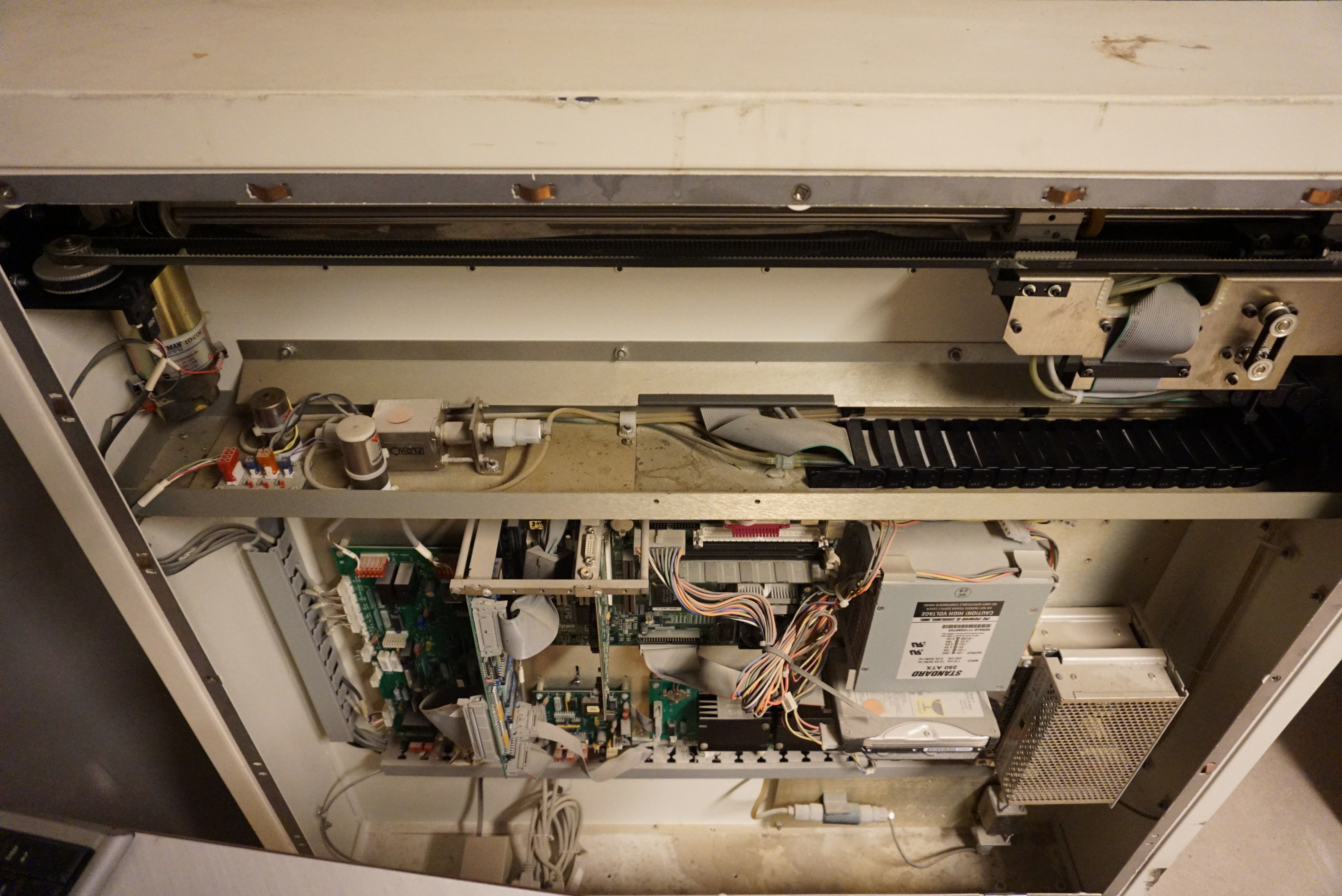
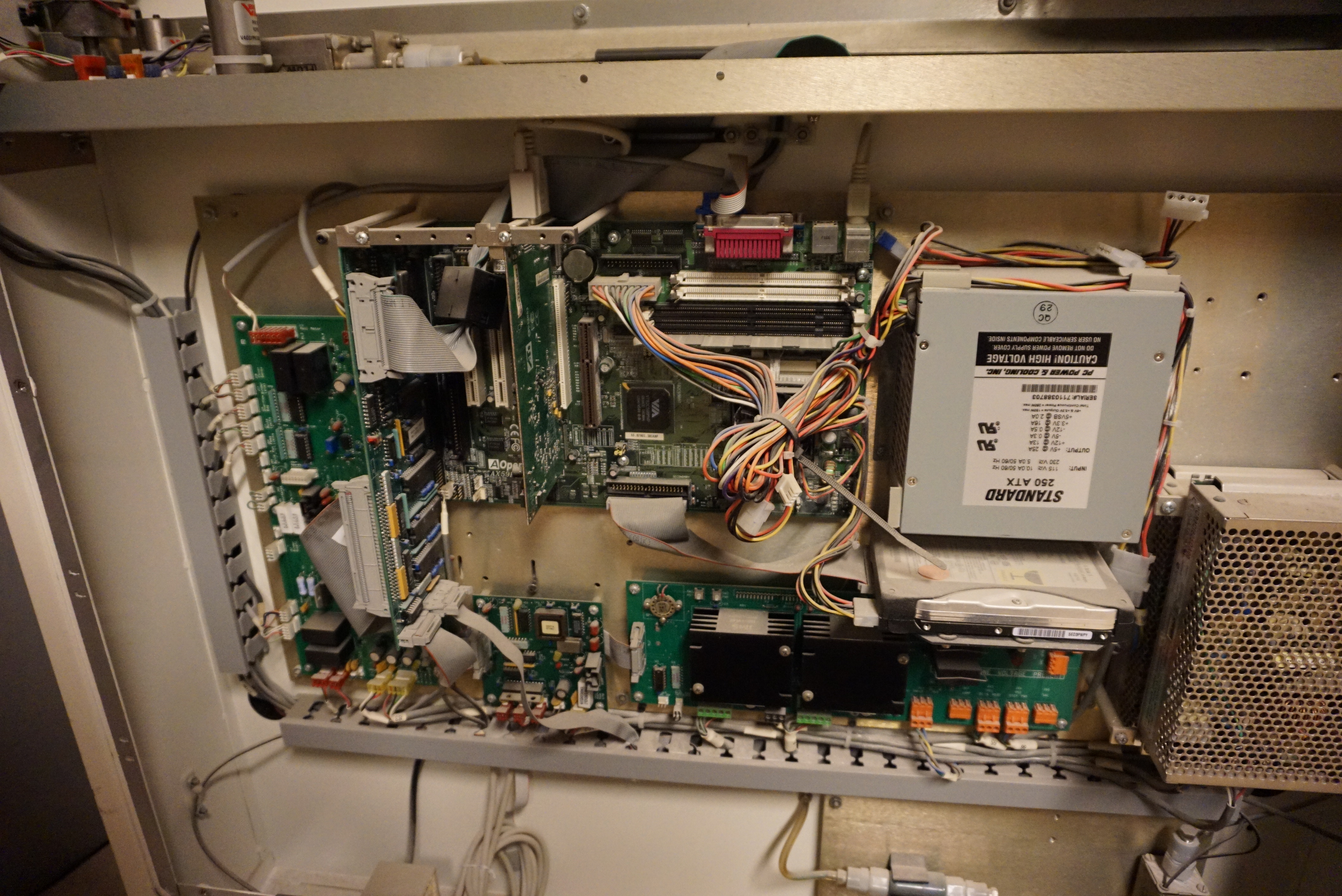
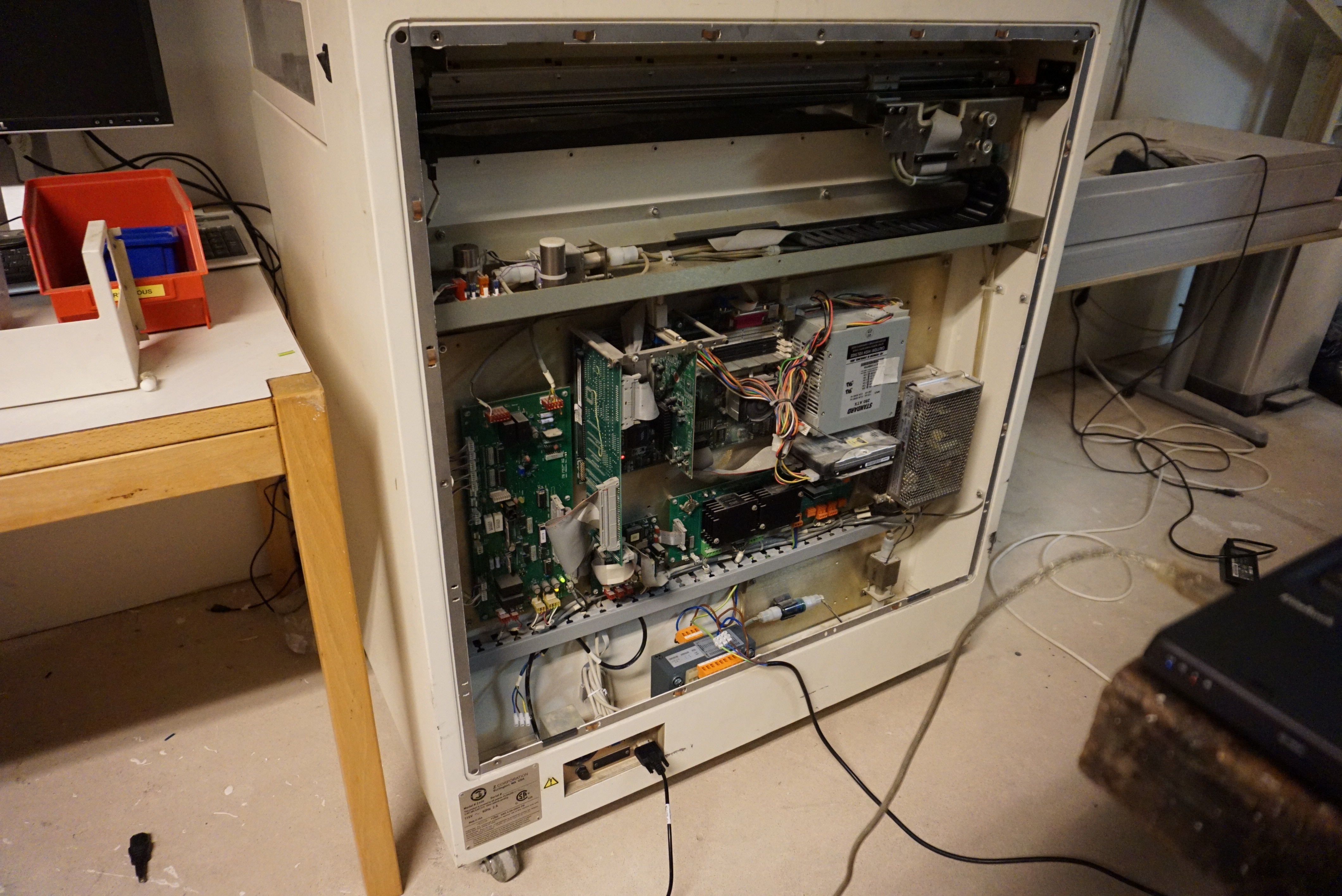
The Z400 is actually a glorified old PC with an inkjet printer attached, and some hardware added to that. It is quite possibly the most amazing hack I have ever seen. “We want a 3D powder and inkjet printer”, and they just took a real existing inkjet printer (not kidding) and built a whole powder handling machine around this. All of this is controlled by a quite normal PC, only with a ISA port to control the actual movement of the machine. It is the way a hacker nowadays would do it, only in this case a million dollar company was founded around it.
The PC insides of a Z400
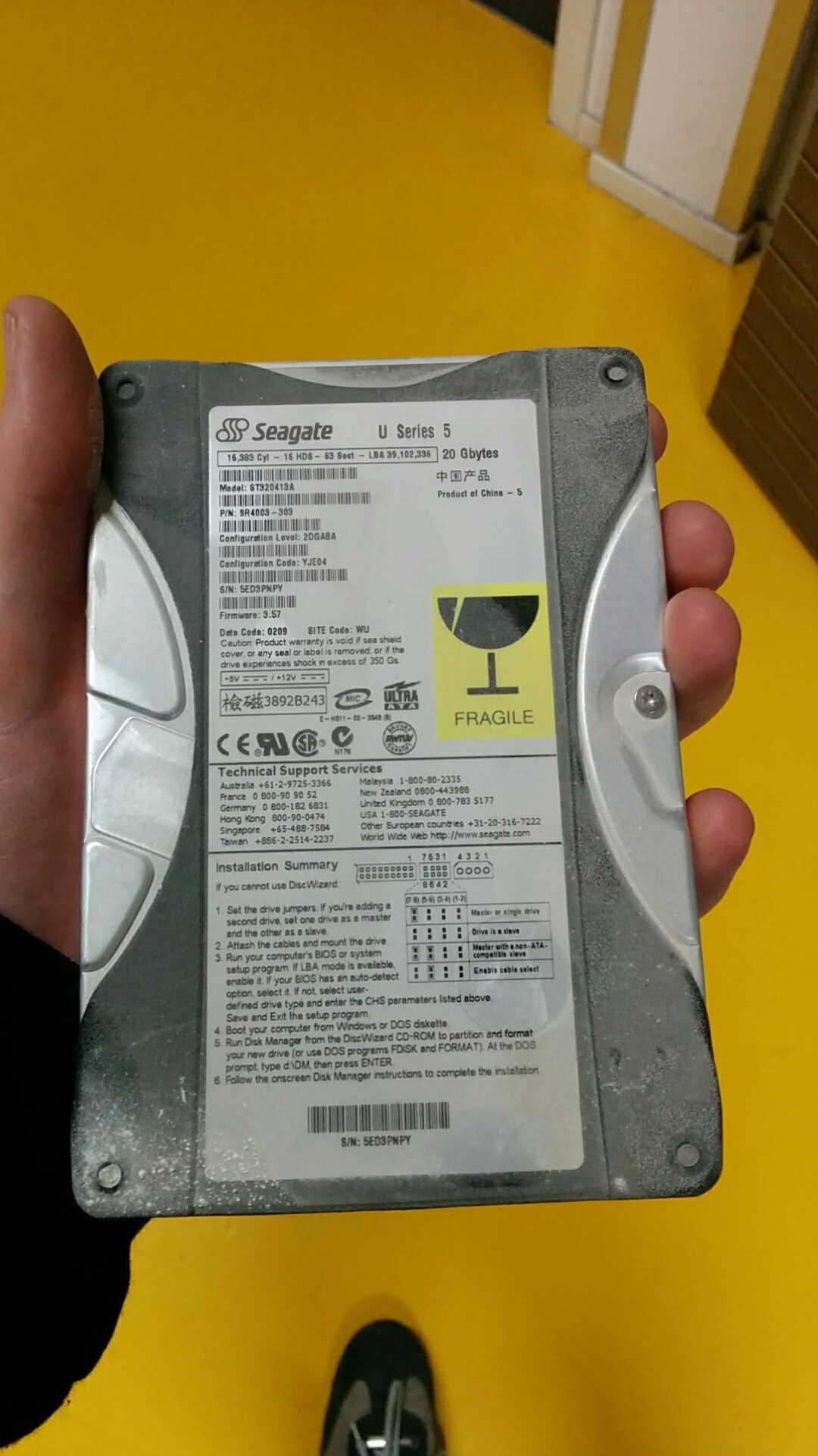
The HDD
The most fragile and least replaceable part is the hard drive. This holds the DOS OS and some software that controls the Z400. If the hard drive is broken without a backup, I can kiss this whole project goodbye.
The hard disc is mounted in the back of the machine. Getting it out is quite simple. Getting an image of the drive was a bit more difficult since it uses an older HDD connector. Luckily the Tkkrlab has a lot of junk, and IDE to USB was quickly found.
And the good news, someone had the foresight to replace the HDD (20GB is not normal in late 90s), and the image seems to be good. One worry less.
For those interested, I do now have an image of a Z400, if anyone has need for this I can send it. A TL;DR is that it is essentially an image of DOS, with some Zcorp sauce added.
Too new for 1998
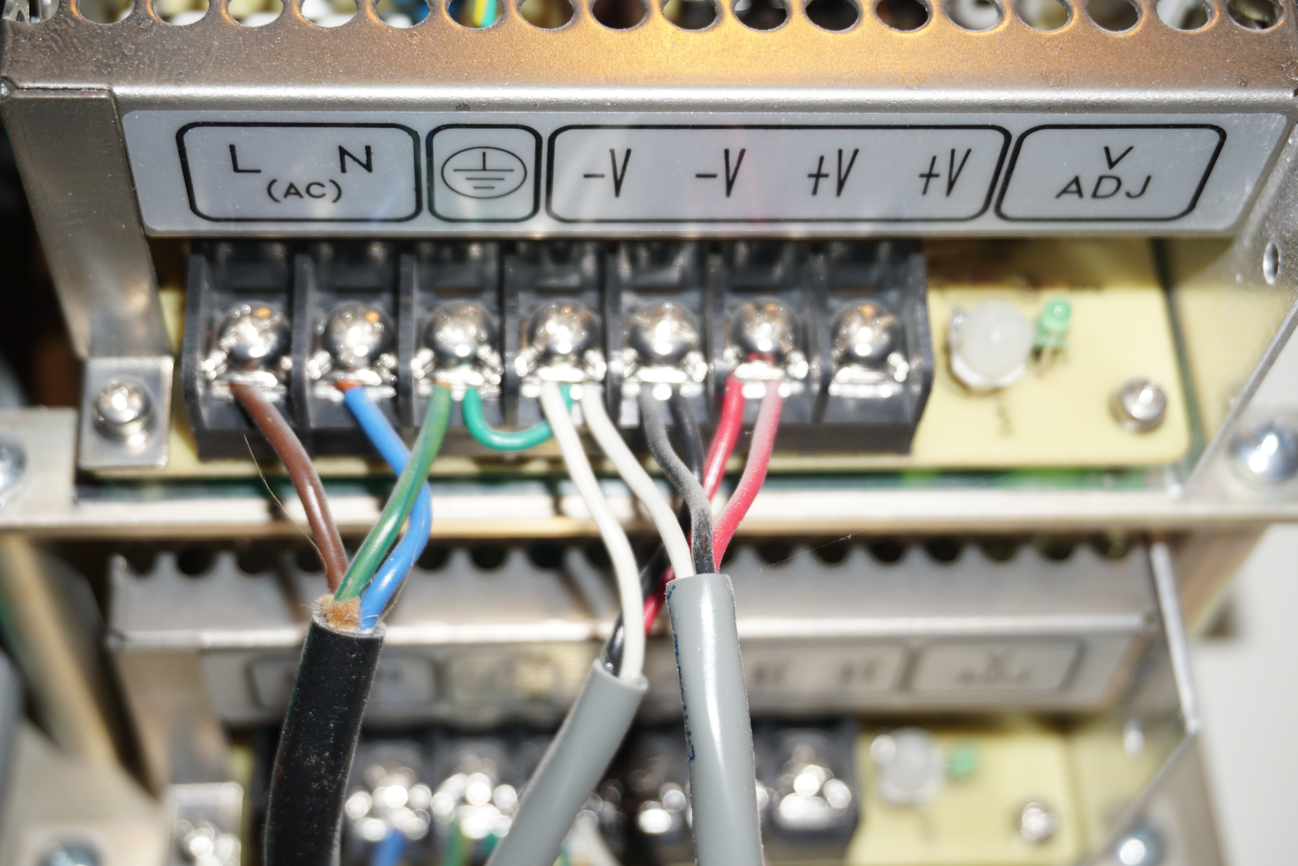
The power supplies
Next are the power supplies. These are around the time a boatload of crappy capacitors entered the market, and even without that issue, capacitors don’t live forever.
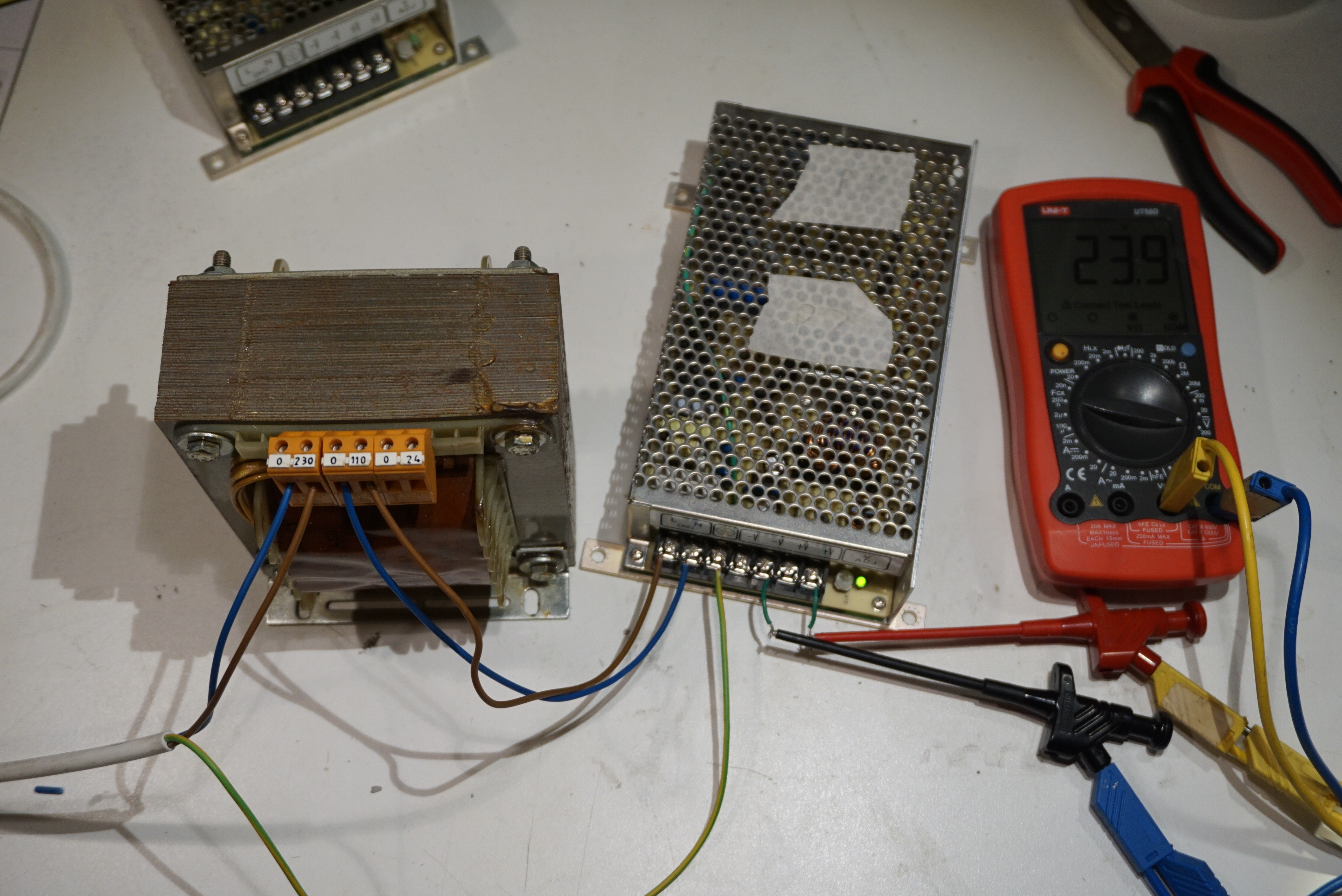
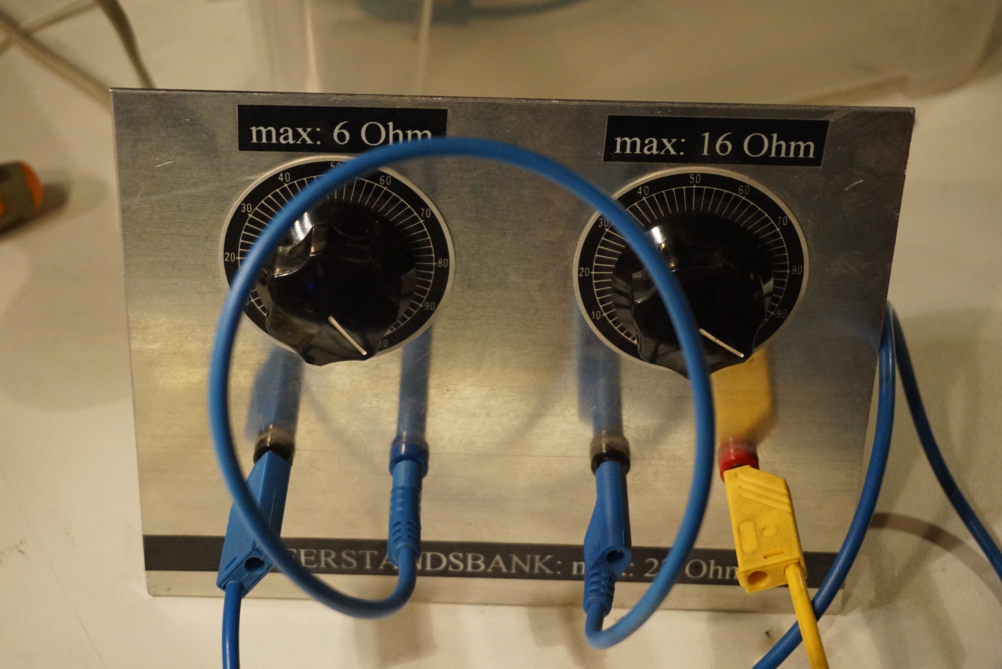
All power supplies (2x 24V and 1x ATX) were removed from the back and separately tested with 115V, the machine voltage. The 2 24V power supplies worked fine under load. The ATX also seemed to be stable, though it was more difficult to test under load.
Negative to ground, niceTesting the power suppliesTest load at 22ohm
To transform, or not to transform
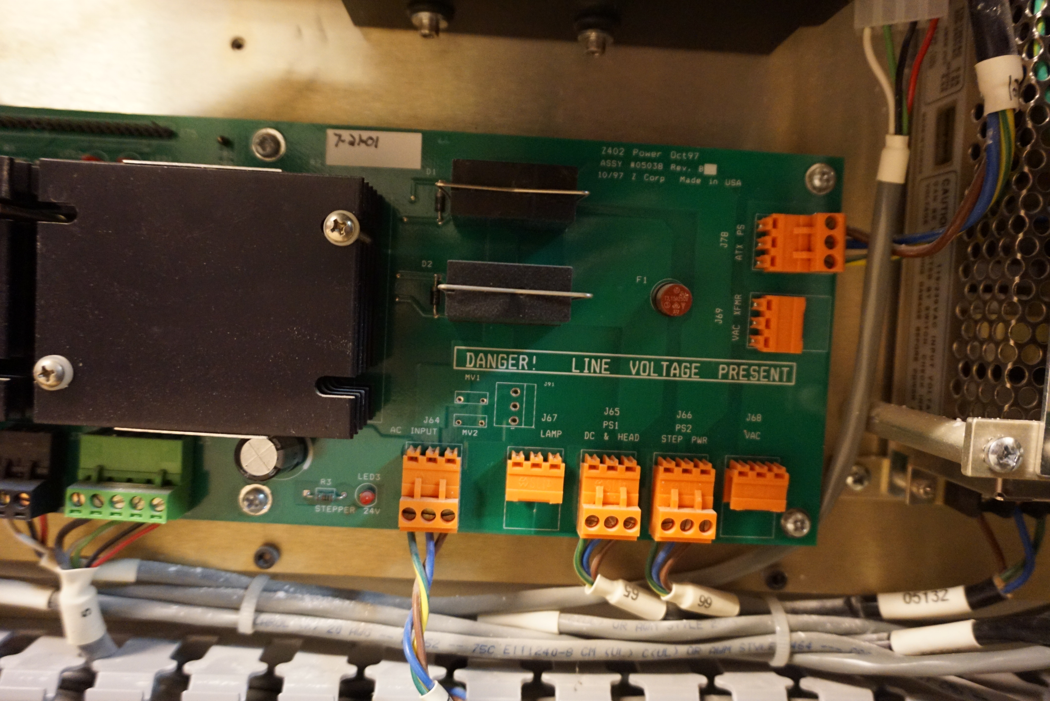
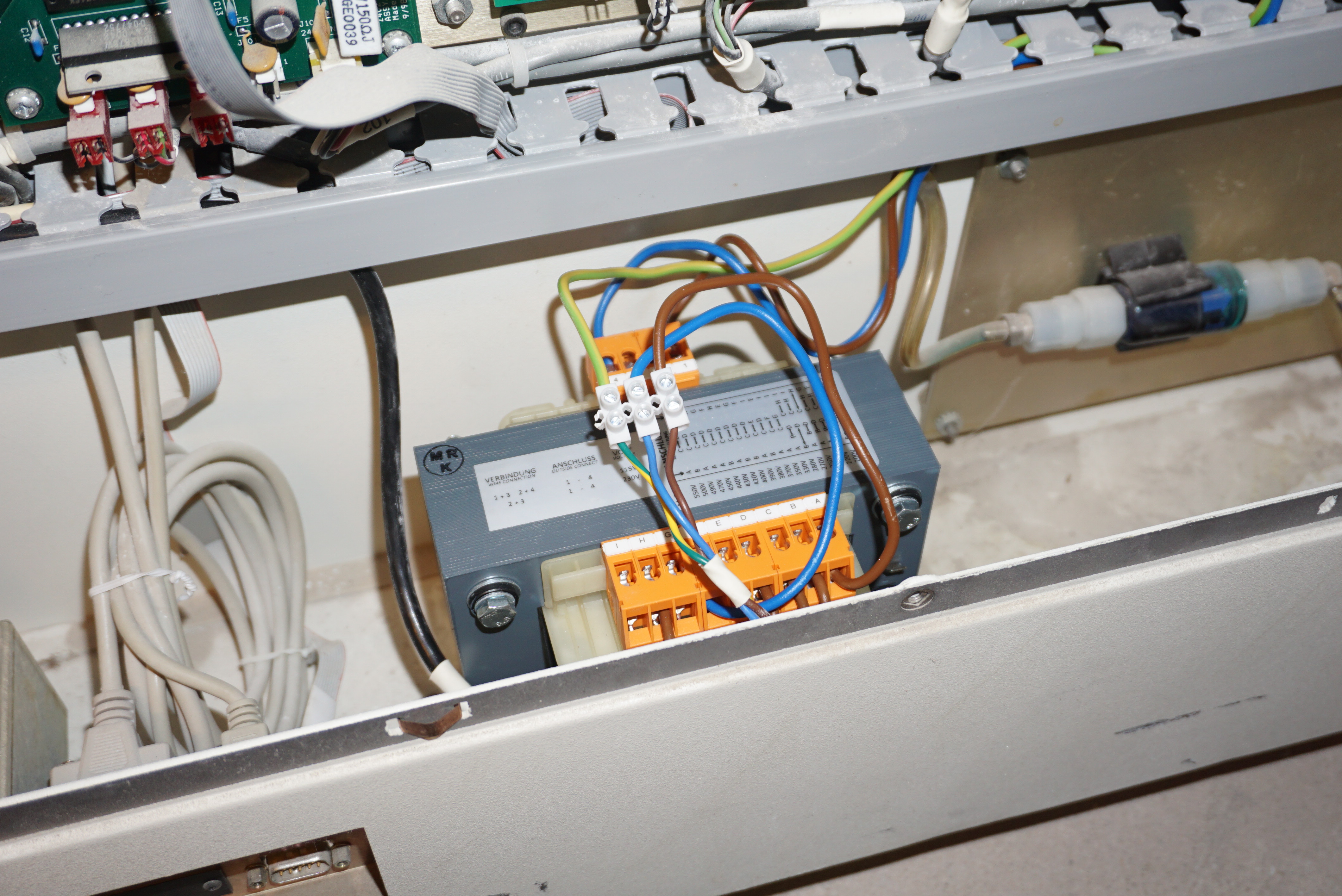
One question remained. How to power this machine. It is an American machine, taking 115V, but I live in the Netherlands, at 230V. The power supplies can all be switched to 230V, no problem. The only issue is that a main board takes the 115V and spreads it to all power supplies. Would I modify the power supplies, or just add a Transformer.
An important part of my decision was made with the manual of the Z400. Here it clearly stated that the 115V machine was 136kg, and the 230V machine was 150kg. The only way this is possible is if the 230V machine has a transformer. A 500VA transformer almost perfectly matches this weight. If Zcorp did not bother simply switching the power supplies over, neither will I. It is very possible that a company selling a monopolized machine goes for the simple solution, but I will not take the risk if I do not have to.
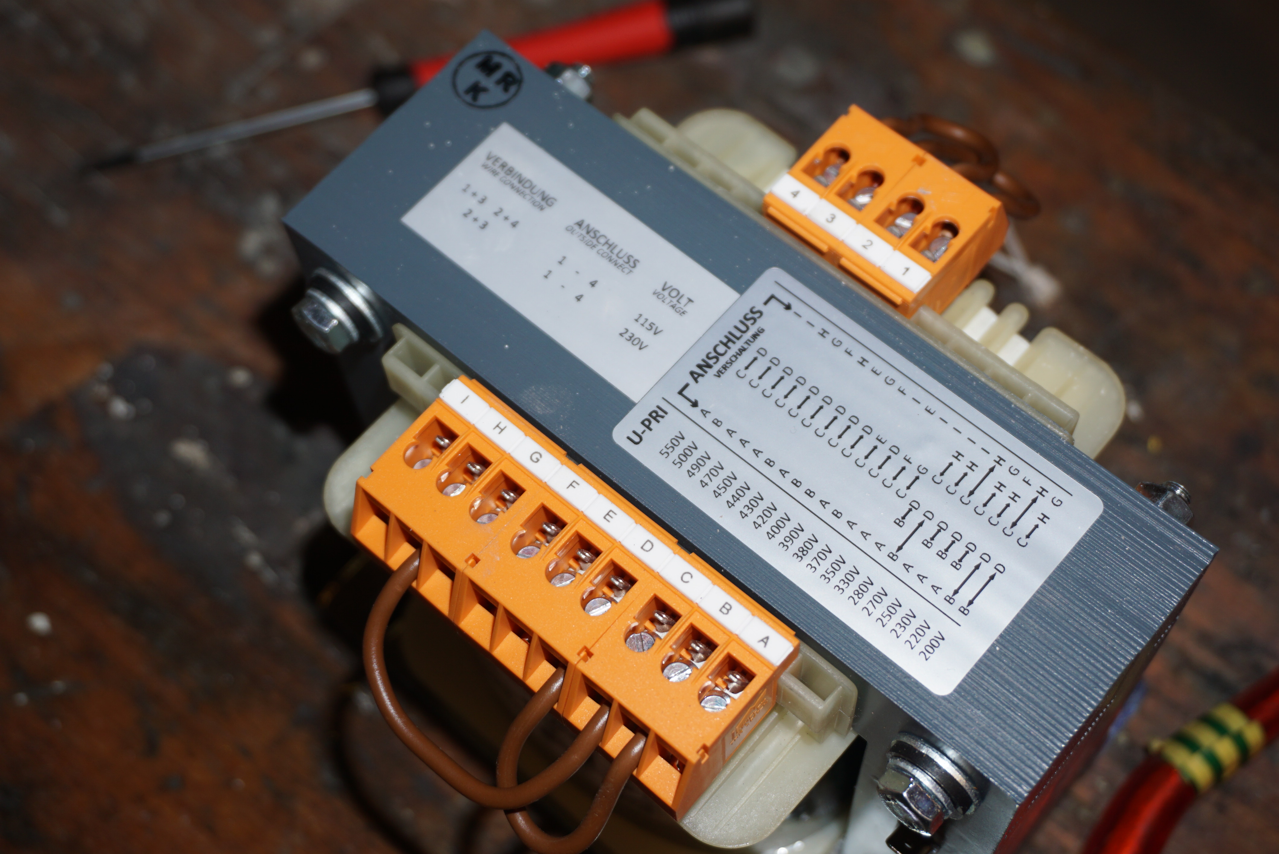
The transformer in question is a nice Riedel 500VA transformer that goes from essentially everything to either 230V or 115V. Exactly what I need. It was mounted in the base, taking the power from the original socket and converting it to 115V before it goes to the main board. There were some flashy accidents with a wire coming loose, and shorting to ground, but other than that, the machine was ready to be turned on.
The board spreading the 115V aroundA shiny transformerHacked in the printerTime for testing
Power
And what happened when we hit the switch? First all leds in the machine came on, then…
Nothing.
The PC does not seem to boot. When we attach a screen, we see nothing, when we attach a serial port, no response. There is light though, and an image on the HDD.
Cliffhanger
This is where to story ends for today. It was getting late, and any next step would take hours. The first step is to take the ISA card out (it is in the way) and see what type of post codes the machine is sending. We are already looking for an ancient PC with an ISA port as a potential replacement. We have everything we might need to make this work. In the next post I will either have something to work with, or a much bigger project.
With no wikipedia article available, there is not a nifty list of features and when it was released, but here goes:
The Zcorp Z400 is a relatively ancient 3DP (powder and inkjet) printer. The manual is copyrighted 1997-2004, so that puts the Z400 at least at 1997. Hilariously enough the user manual completely fails to mention how big the Z400 can print, but it’s probably around the size of an A4 (200x300mm) by 200ish vertical. Once I know, I will say.
Also quite interesting is that the whole mechanism of the Z400 says ‘robust’ and ‘industrial’ until you reach the printhead gantry. The whole gantry is sheetmetal from an ordinary old inkjet printer that uses Canon BC-20 printheads. The Z400 uses modified versions of this BC-20 that are no longer available, but there are alternatives to make yourself: http://blog.freesideatlanta.org/2011/07/making-print-cartridges-for-z400z402-3d.html
The BC-20 heads have no DPI known, but should be 128 nozzles since the manual speaks of 128 jets of binder. Again, will say when I know.
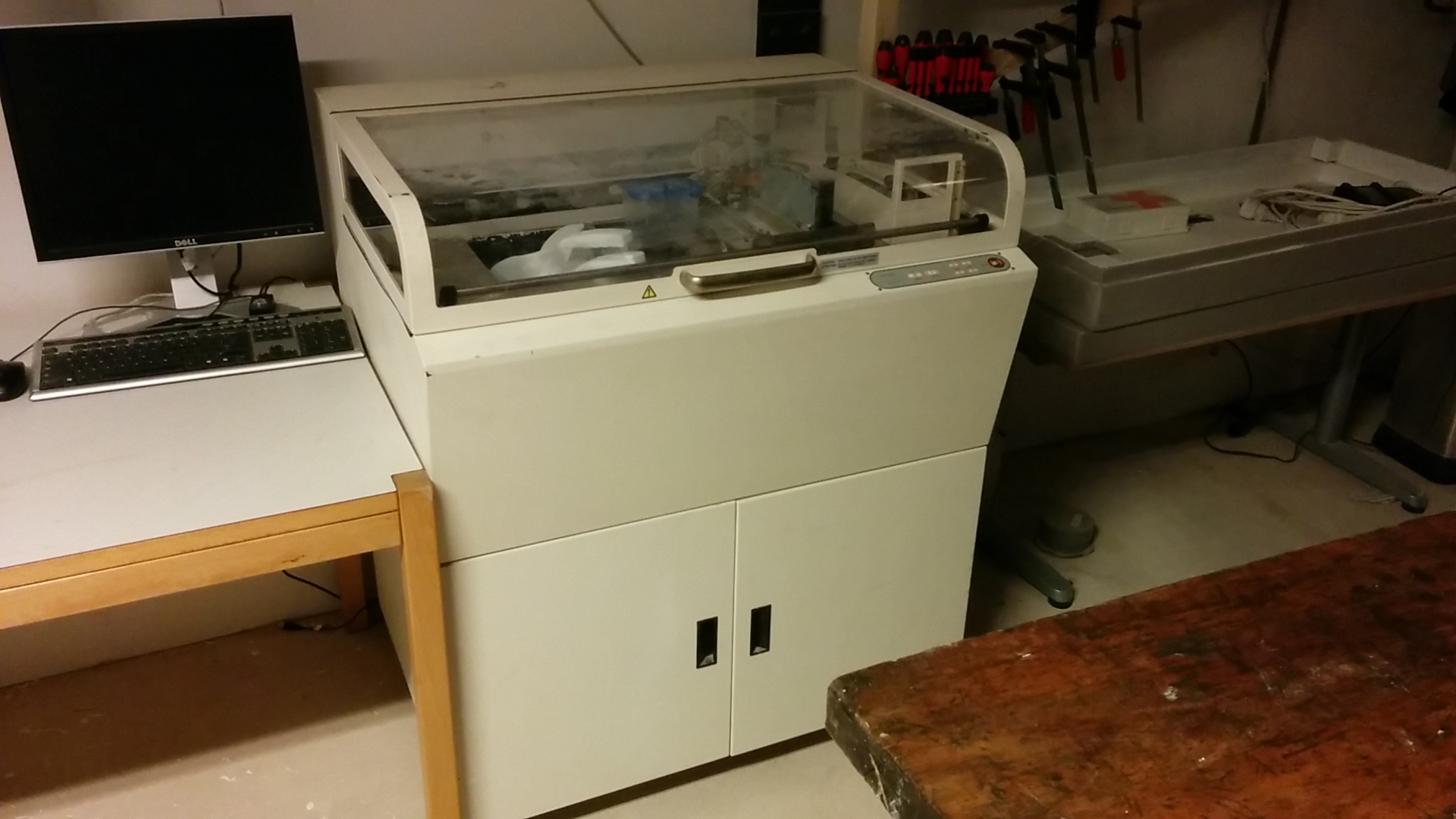
A summary of the Zcorp Z400 is that it is a big standing 3DP printer from the time when 3D printing was unheard of, running an old PC (more on that later) controlled through serial, controlling a hacked Canon inkjet printer to print in powder. There are plenty of motors and pumps and pistons to make it all work, but that is the summary.
Looks nice and robustLooks like someone hacked an old inkjet printer (they did, not judging)
Why and how I got it
“But Yvo”, I hear you say, “how did you get this Z400?”.
Wonko donated it to me. It has not been running for half a decade and he wanted it somewhere where it might be used. Getting it to my house was quite an adventure, revolving around a too light car, a too big trailer and a town celebrating carnival.
It currently sits at the Tkkrlab in Enschede while I repair it.
What I want with it
Obviously I want an working 3DP printer from a real original 3DP printer builder. And since there are boatloads of patents involved, there are only 2. Zcorp, and the company that bought Zcorp, 3DSystems.
I got into 3DP because I love the concept of 3DP, and my goal is to print ceramics with this. I will investigate other materials, and will continue work on my own 3DP and inkjet adventures, but I also cannot pass the opportunity to get experience with an original printer.
What needs to be done with it
The machine has been sitting still for the past few years and is already old by itself. There is no guarantee that this blog will end at page 2 proclaiming the PC as dead and irreparable. But I will try my best to make the original work, and else replace all that is printer with my own electronics.
This is the short list of what needs to happen before I can even start to print:
HDD needs to be tested. If these fail, the printer is dead. (Spoiler alert, I did already make an image of my drive, this still works);
Power supplies need to be tested outside the printer (it is a 110V machine);
Computer and boards need to be tested. The computer needs to start and run, and the printer needs to want to move at least;
Binder lines and printhead ribbon cables need to be tested and or replaced;
All movement needs to be checked and lubricated. The build piston probably needs a new seal;
Printheads need to be made;
If I did not forget anything, that is what I will need to do before I can start to print. Here is hoping that the machine is still in working order.
It is getting better, 16 people reading this. The last post was in May, only 7 months ago.
Oasis 3DP
The Hackaday prize is done, and so is Oasis. Did I win the contest? Nope, but Oasis is now printing, which is also really important to me. There are still plenty of thing left to do on Oasis. The firmware and software need more work, I need to study materials, I want to be able to sell printhead controllers when everything is more stable, and I do have lines open for better printheads. All things I can do in 2019. These updates will not happen within the first month of 2019, but I am working on it. Oasis for the foreseeable future will only receive small, incremental changes. I do hpe to write a more complete page on Oasis on Ytec in 2019 as well.
What else will I be doing in 2019? The first thing I want to do in 2019 is finish the Turret, mentioned in the previous blog post. This will take me a few months, so do expect a bit of radio silence on that, but I hope to be done before April. I also want to finish the robotic board game, also mentioned in the previous blog. It has less priority, and might not be finished before the end of 2019, but I do hope to finish it in 2019.
There are plenty of other, smaller projects I am currently working on. These range from domotics hardware (I have domoticated my house, and hope to do more with it), some small electronics projects like hexagonal matrix displays, and heat exchangers again. As always, none of this is set in stone, but that is what can be expected in 2019.
I will post more on the site again. I have been more on Hackaday.io last year, and might keep doing stuff there as well, but I do have this site, and I like working on it.
I really should, The last post was in 2015. It is not like I am dead or anything, just busy.
On what you might ask, one of the 15 people reading this? Glad you asked. There have been 3 massive project that have taken most of my project time the last year or so. All 3 are still set to be finished somewhere this year (or early next year) and all 3 are awesome. The projects in no particular order are:
Oasis 3D printer
A powder and inkjet 3D printer, 4 years in the making. After I finished Plan B I set myself the goal of making a newer, better’er 3D powder printer with newer hardware. This hardware was the HP45, and this printer was Oasis. In those 4 years I have done a lot of work, but I have failed to make a new 3D printer. Setbacks, feature creep and me being distracted has made sure that no new 3D printer does yet exist. There is good news though. I have entered the Hackaday prize with what I hope to be a real attempt. I have already made it to the finals, so I think I am committed now.
(The printer is actually further than this, but click the hackaday link for that)
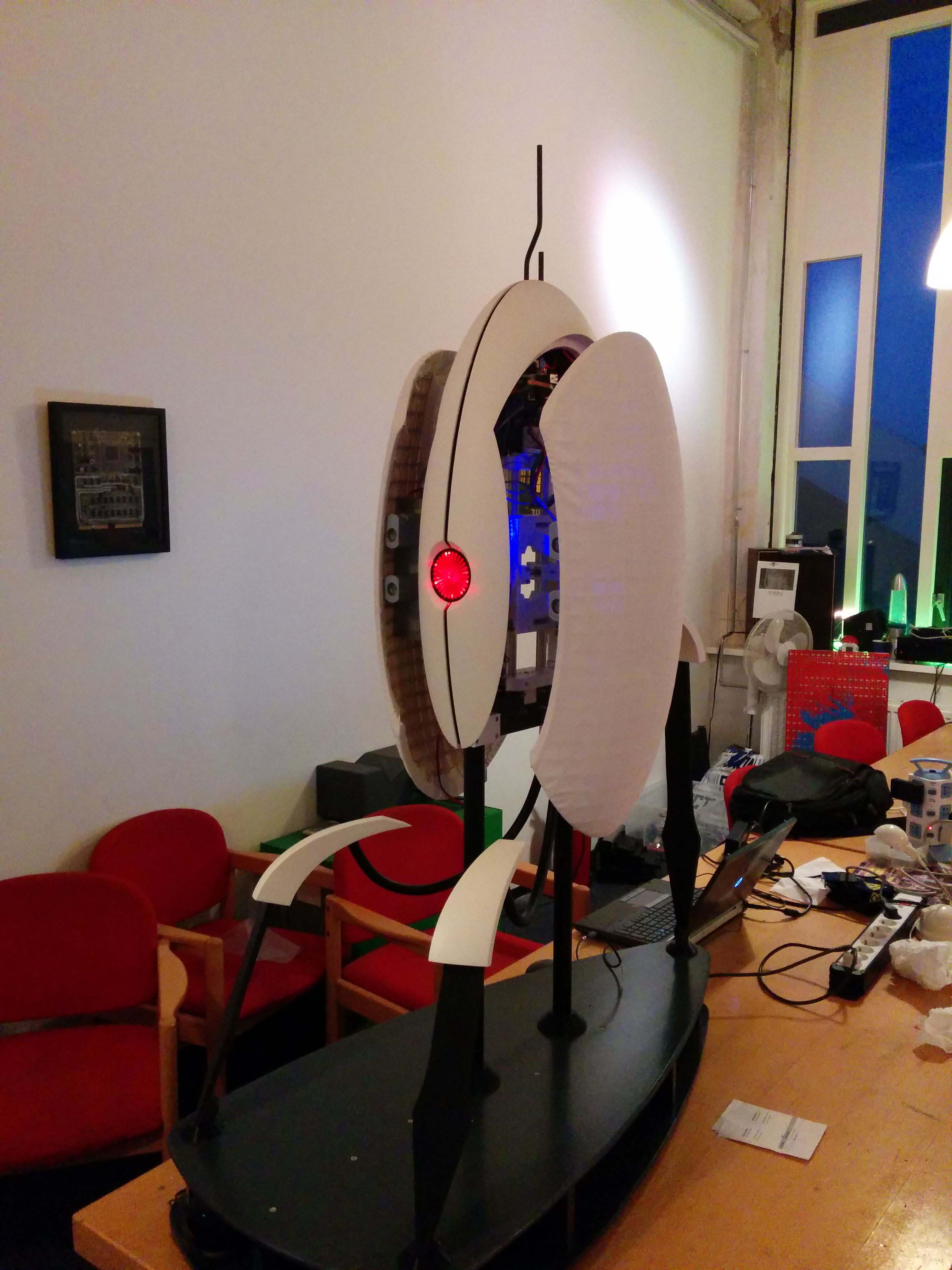
Full scale Turret
Did you know we had a turret (running gag at my local hackerspace). For SHA 2017 we (I) wanted something awesome to show off. When we made the decision to make something, I had about a month left. That something that was going to be made was a full scale, opening and closing, talking, watching, shooting turret. To all the people that said that it can’t be done, you are right, but only just. Mechanically it was done, it was shooting, it was moving, it was awesome. It just was not finished. The mechanism jammed, the electronics failed constantly and the software was basically non existent. After spending every waking hour for a month on the Turret, I did not feel like finishing it. Was going to start this March, but then the Hackaday prize happened. The turret will probably be the first thing I will work on after Oasis, and I promise it will be awesome.
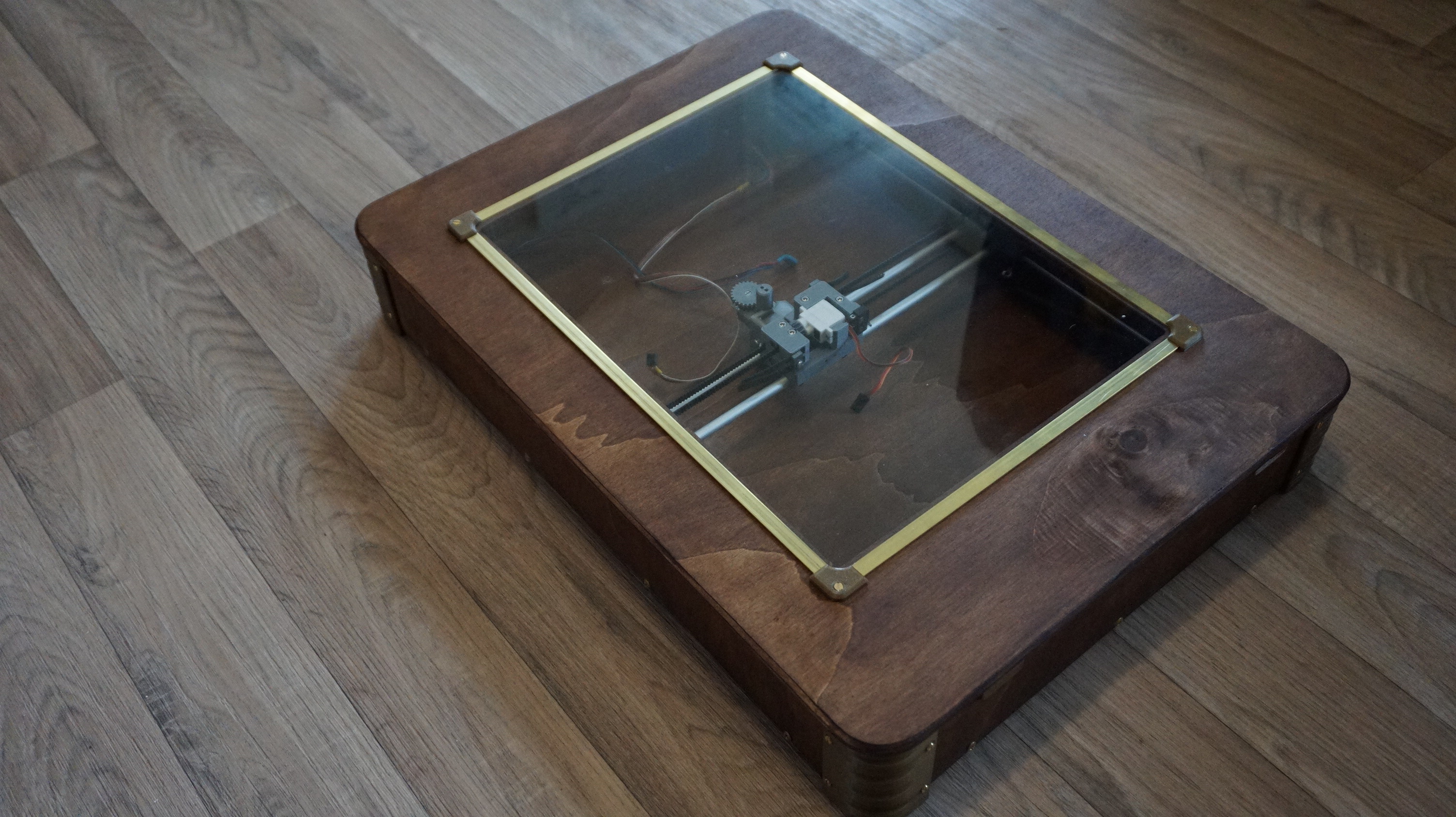
Robotic boardgame
The answer when playing roborally and not wanting to move the pieces constantly. This let met to start on one of these ‘a lot bigger than they seem’ projects. To make a robotic playing board that can move pieces in a game of roborally. The game has a gantry with magnets and cardreaders to read the playing cards. It actually moves just fine, only the game rules firmware and the cardreaders are left. The thing that stalled this project was that I moved. If it weren’t for that, I might actually be finished. After moving I wanted to work on something else first. That was the Turret, and then Oasis. This project will probably be finished after the Turret. It does not have the same grandeur as the Turret, but is still really neat.
And now that I have posted and thought about posting more often, it will still probably be a year before I post again. Until then.