The Spin Meister is a speed adjustable motor to spin the pizza stone in an Ooni Koda 12 pizza oven. It has a stepper motor to drive the stone through an attachment in the bottom of the oven. The controller controls the spin speed and cooking time, and information like remaining time is easily readable on a state of the art VFD display that has a whopping 12 characters. Sliders control the spinning speed of the stone and the cooking time, and the process is started with 2 easy to reach buttons. The whole project is powered from a power bank, for perfectly spun pizza wherever you are.


The Spin Meister consists of a controller attached to a stepper motor. The stepper motor has a bit holder that simply attaches to a bit mounted to the pizza stone, located under the pizza oven. An aluminium brace stops the motor from spinning in place.
A USB C power bank provides the power for the controller and the motor. There is no on/off switch, simply plugging the controller in powers the controller.
On the controller there are 2 buttons, spin and time, and 2 sliders, also spin and time.
- Pressing the spin button will start the stone spinning. Pressing the spin button again will stop the stone spinning. If a timer is running stopping the stone will also stop the timer.
- Pressing the time button with no timer running will start a timer at the set amount. Pressing the time button again will add 10s to the time.
- Moving the spin slider will set the spinning speed of the stone. The numbers are a bit arbitrary (steps per second), but 200 should make the stone spin a full rotation every 16 seconds, while with 100 a full rotation takes around 30 seconds.
- Moving the time slider will set the time the timer takes when started. The max time is around 5 minutes, in 5 second steps.
- Pressing the time and spin button at exactly the same time allows the user to set the volume using the spin slider. The volume is adjusted live, and after 10s the controller automatically returns to the main menu.
- Pressing the time and spin button at exactly the same time, while both sliders are in the left most (lowest) position activates party mode. In party mode music of your choice will play when the timer is running.

Design choices
I want to share my design choices before sharing the design files because the Spin Meister was made with some very specific requirements and some specific choices. So below a list of some of the choices in no particular order.
- I already own an Ooni Koda 12 with an after market rotating stone. The mechanism in question is this one here, the ZIFA Grills Pizzatwister. Since I already owned that, I did not feel compelled to buy a ready made motorized revolving stone, which is actually just available.
- I own too many stepper motors. I built plenty of 3D printers back in the day, and quite frankly I have too many steppers. A DC gearmotor would have worked equally well, and be a lot cheaper. The only real benefit of a stepper motor is that I can carefully control the speed.
- I had the VFD screen lying around after getting it from a friend, just begging for a project. You can get the screen yourself here.
- The project needs to be powered in random places, sometimes without easy power available. I do own a 20W USB C PD power bank, so this should power the Spin Meister.
- The Spin Meister needs to be removable from the oven so the oven can be used without it, and so that the oven can be transported. Toolless attaching and removal is a big plus.
- I wanted an adjustable timer. Being able to walk away from the oven and be warned that you need to come back is a feature I really wanted. Since I needed an alarm, I wanted to make sound, but really didn’t feel like messing with buzzers. So I added an MP3 player module, which allowed for other dumb features.
- Minor modifications to the oven, like drilling holes is absolutely fine.
- Big buttons that are easy to press with messy hands.
- Potmeters to adjust the settings, so that there is no complicated menu.
Making one
Before anyone tries to replicate this, be advised that this project is not really designed to be replicated. It uses parts I had laying around, including some decades old parts, and uses specific components and tools that I have easy access to. I do share the data and design files for inspiration and for reference, but do expect challenges and modifications on your side if you do try to replicate.
With the warning out of the way, here are the files:

Mechanical parts
The mechanical parts consist of 3 basic parts. Getting a bit attachment attached to the stone and out of the Ooni, getting a bit holder attached to a motor, and the housing for the electronics.
Hub
The Pizzatwister that is in my oven has uses a mating screw and some washers to provide the spinning mechanism. This is simply stainless steel and a tiny amount of grease providing the bearing. It seems too little, but it holds just fine, so I do not feel guilty using a similar principle.
I used a lathe to make a replacement part that attaches to the spinning stone. I used stainless because it is harder and more tolerant to heat, but given the low velocity and relatively low temperatures at that location, brass or even aluminium might work. This machined hub has a torx bit pressed into the bottom to mount the bit holder to. This hub is attached to the stone plate with screws.
A hole is drilled in the bottom of the Ooni to provide a pass through. The pizza stone with the hub is placed in the old frame, and washers and a collar is used to hold the hub in place. A small amount of silicon grease was used to lubricate the hub.
(In using the oven, the hub never went much above 30C, so it seems that while the stone gets 450C, the original parts of the Pizzatwister do a decent job keeping the heat away from the hinge)


Motor
A latching bit holder was bought for this project. A good portion of the hex was removed and a 3D printed PETG holder was made to link the bit holder to a stepper motor. M3 nuts and grub screws were used to fix all parts in place. I first considered making the mounting between the motor and the bit holder on a lathe as well, but given the low temperature, I never did.
The motor got a torque arm made from a strip of 20x2mm aluminium to stop the rotation of the motor.


Electronics housing
The electronics and interface needed a housing. This housing was printed out of PLA and PETG. The files are included. They are not oriented, and some parts need to be split.
Most parts are pretty self explanatory, but there are some quirks.
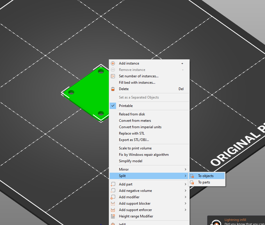
I do tend to put a few parts in a single STEP file. This is because it makes my work designing the parts easier, and my slicer, PrusaSlicer can easily split the file in several parts by right clicking a part, and then: “Split > To Parts”
The grills for the speakers are made using the slicer. Each grill consists of 2 parts, the frame and the grill. To make the part, you:
- Load the model into PrusaSlicer and orient correctly
- Then you right click the model and press “Split > To object”
- Select the center of the part, go to the right and select “Infill” and “Layers and perimeters”
- Set the infill for the center to honeycomb, and the top and bottom solid layers to 0. The perimeters need to be set to 1.
- You can adjust the infill percentage to adjust the size of the holes
- After slicing, you should now have a nice looking grill.


Electronics
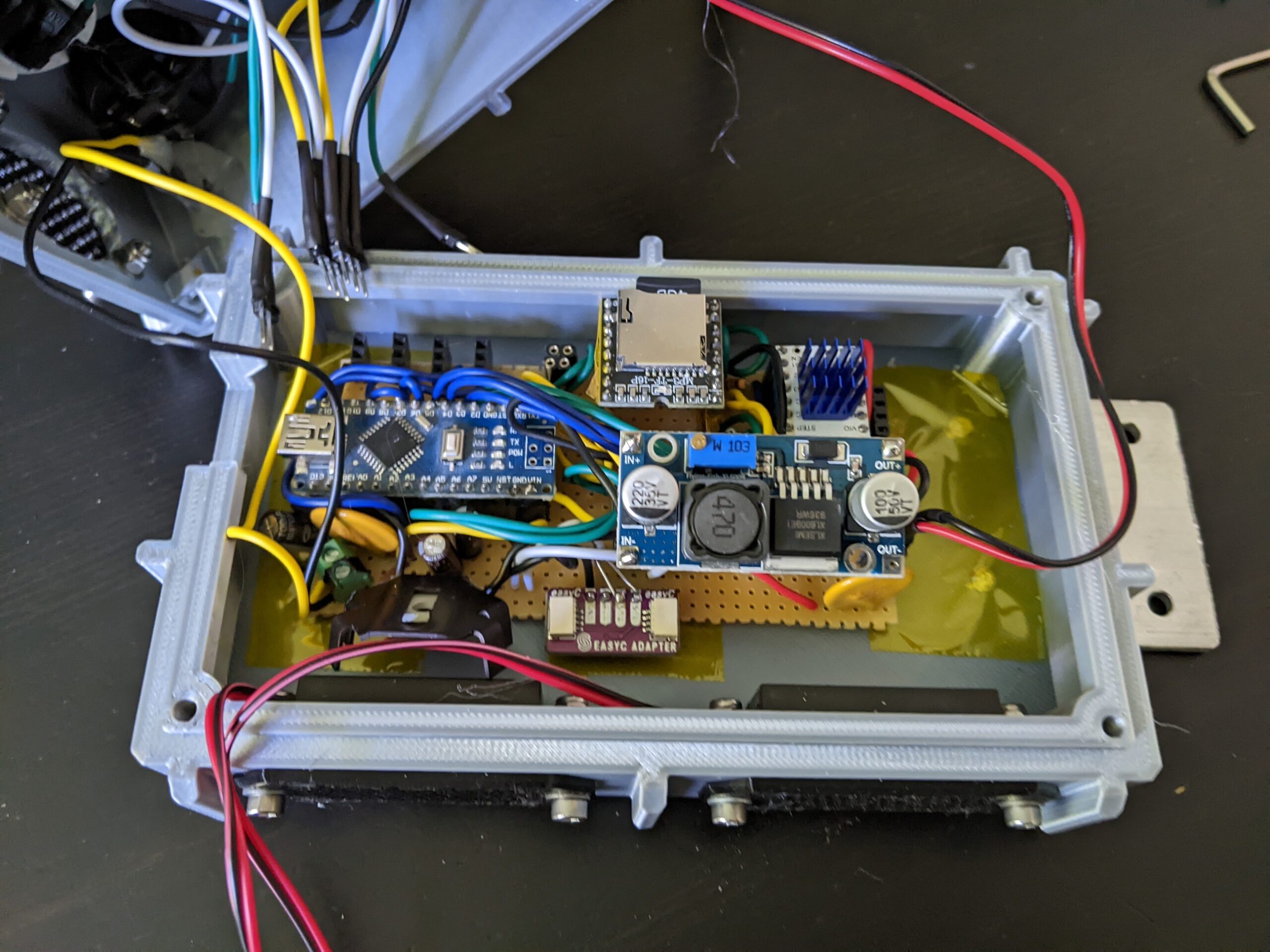


PCB
The PCB needed to be done quickly, and I needed only one. For this reason, it was made entirely on a prototype board. Other than a photo of the result, and a schematic, I do not have much more to offer. Some notes on the design.
- I use the USB C PD trigger circuit to get 5V 3A from the powerbank. In hindsight I should have used a different board because the one I got only does 5V, 15V and 20V, while my powerbank only does 5V, 9V and 12V. I would have loved to use 9V or 12V and then only step down, but this is what I had.
- The 3.3V is made with a linear regulator. I underestimated just how much the VFD uses (around 0.5A peak), so in hindsight I would have used a step-down regulator. The 1A version I have does not get too hot, so it is fine.
- The stepper motor voltage is made with a boost converter. I set it to around 10V.
- If I set the motor current on the silent stepstick (TMC2100) wrong, the voltage does cut out, so I only have limited power for the stepper available. It is strong enough at the current setting though. This is probably the 5V 3A from the powerbank that is too little.
- I put a 30mm fan in the housing just in case. I am dissipating quite a bit of heat in there.
- An Arduino Nano was used to control everything. The only reasons for this is familiarity and availability.
Wiring
All components, the screen, the buttons, the fans and the potmeters have headers attached to them. The PCB has the corresponding headers on it. None of the connectors are latching or have a polarity, so you can mess up plugging the parts in. The screen uses a Qwiic connector, which makes life quite easy.
Housing assembly
There are no real images of me assembling the housing. The screen and potmeters, as well as the USB C connector are simply hot-glued into the housing. The fan and the speakers use M3 screws to mount them, and the buttons simply lock in place.
The bottom uses M3 screws to mount into the top part. I had to drill out the holes to make my screws fit. I also added an aluminium strip to the bottom, which I use to mount the controller to my oven table. This part is specific to my needs, and is highly optional.
Firmware
The arduino firmware is included in the project. It is nothing special, and has little to adjust. For the MP3 module there are 3 defines that really matter:
- #define FOLDER_CLICK_SIZE #
- #define FOLDER_DONE_SIZE #
- #define FOLDER_MUSIC_SIZE #
Where # is the number of MP3 files that are on the SD card. The software is a bit dumb and not capable of reading the number of files in each folder, so you have to tell the firmware (and update this value each time you add or remove songs to the SD card). CLICK should realistically be one file, but DONE and MUSIC can be any number of files.
DONE plays after each time the timer is done, and picks randomly from the folder to play once.
MUSIC is the music for party mode. It will pick a song from the folder and loop that until the timer is done. Songs that loop well or are long enough for a single timer are advised.
MP3 module
The MP3 module, the DFRobot DFPlayer Mini MP3 Player is an easy way to play MP3s from an SD card. The module is controller via serial, and can directly drive up to 2W of speakers or has an amplifier output.
The file format is described on the site here, but the TL;DR is that you need to have folders named “01”, “02” and “03”, with the MP3s to play named “0001.mp3”, “0002.mp3” etc. In theory there is a function that returns the number of files in each folder, though this function works poorly for me. I simply add the number of files in each folder as a #define in the firmware. Each time you add files to the SD card, you need to change this number and flash the firmware.
- The folder for the click sounds is “01”. This stores the sounds played when you press a button. The firmware can only handle a single file here at the moment.
- The folder for the finished sounds is “02”. These sounds are played when the timer runs out.
- The folder for the music while running is “03”. This stores the sounds played while the oven is in “Party mode”, while it is cooking. It is advised to have all songs related to spinning, hotness and pizza stored here.
For reasons of me not owning any sounds, I have not included the sounds I am playing, so be creative and look for sounds yourself.