The HP45 is quite a remarkable piece of technology. On this page there is an in depth view and teardown of all the elements that make up the HP45. This is a mix of internals, technical information and microscope closeups.
This page will have quite a bit of overlap with the original HP45 page on this side (https://ytec3d.com/hp45-inkjet-printhead/). This page is more recent and includes more of the details of the printhead instead of how it works.
The outside
Body
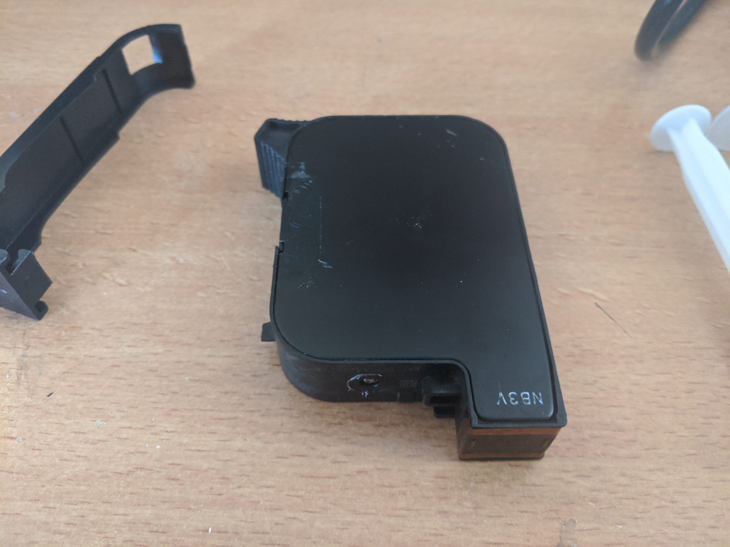
The main part of the printhead is the body. This is basically the ink tank. The body consists of a hard plastic rim, and thin sheet metal on either side. On the bottom there is a protrusion for the nozzles, and on the bottom next to the nozzles and on the top there are alignment features. At the front is something of a handle.
Also on the bottom, hidden under a sticker is the fill port of the HP45. The printhead is capable of printing more than the given ink capacity, and so some of these printheads are refilled. Under the sticker sits a ball pressed into the port to seal the printhead.
Supplied with the printhead is usually a plastic clip with a sponge. This fits around the printhead and seals the nozzles, preventing them from drying out.

Contacts
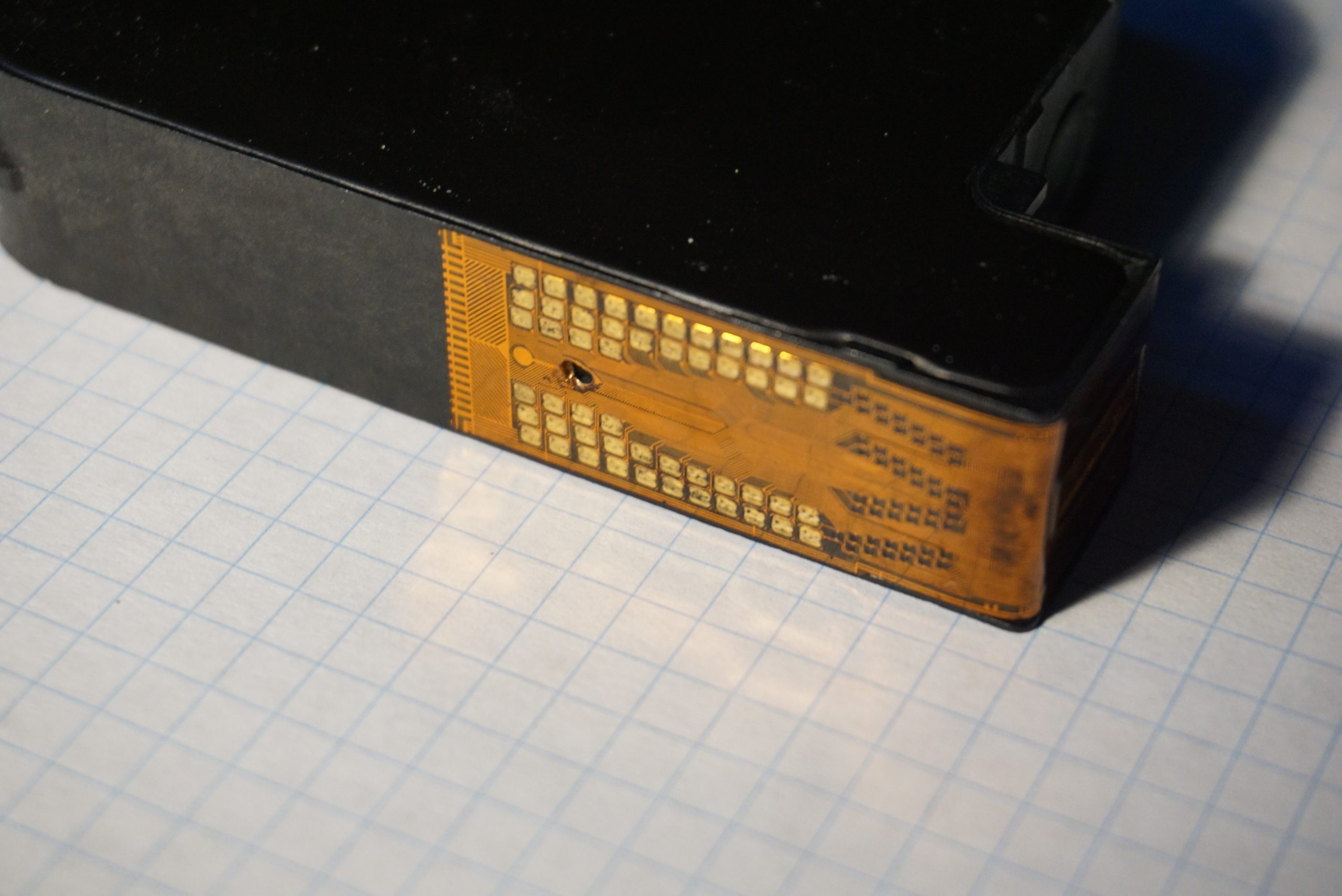
On the back there are 52 contacts, 26 on each side. These contacts are used to connect to the matrix of nozzles in the printhead. The contacts are on a piece of flexible PCB which also connects to the actual printhead die that holds all the nozzles and electronics.

Nozzles
The nozzles are the thing that eject the ink. This is done by flash vaporizing a tiny bit of the ink to create a steam bubble. This bubble will eject the rest of the ink from the chamber. This vaporization happens fast, happening in less than 2 microseconds.
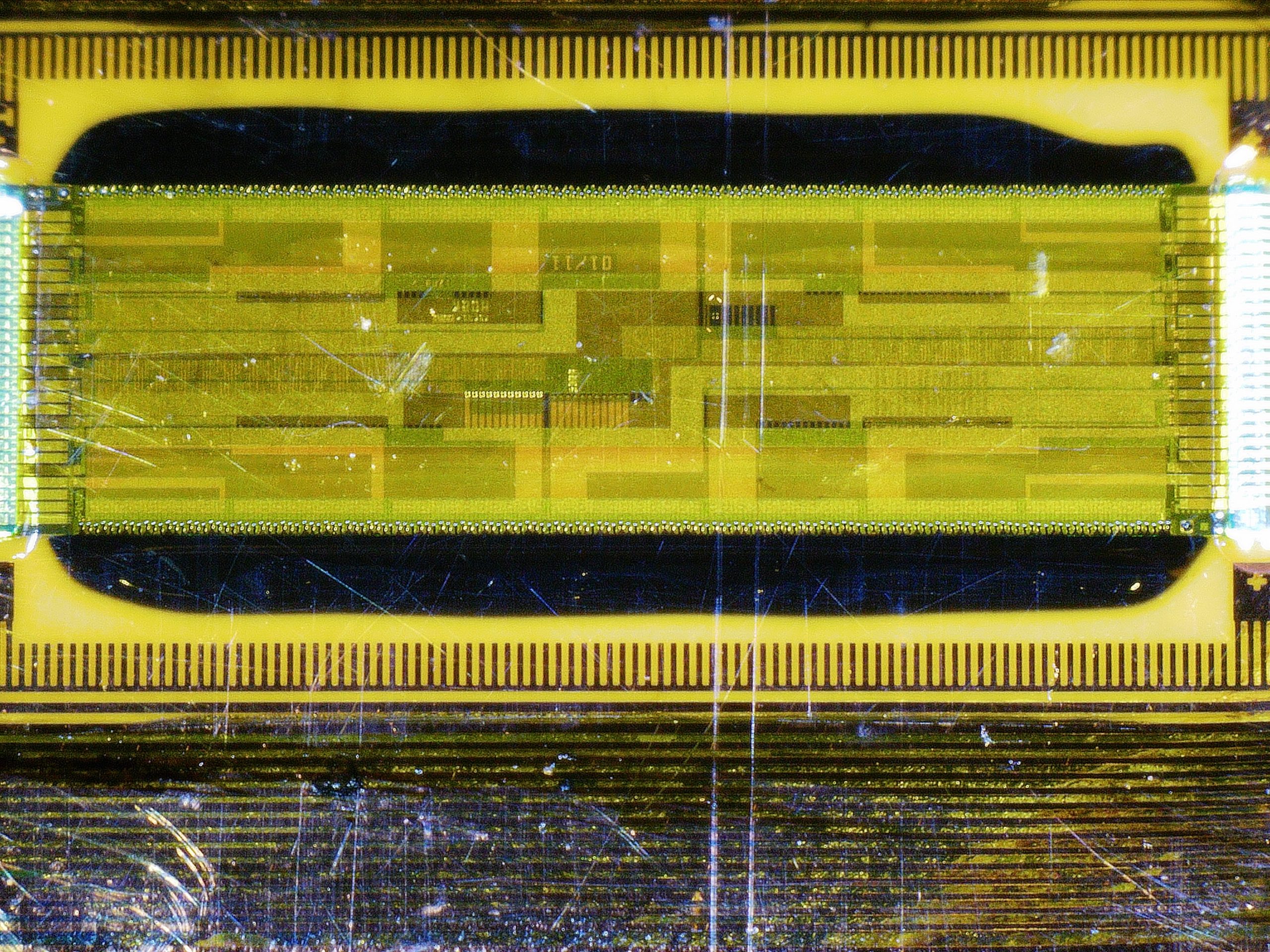
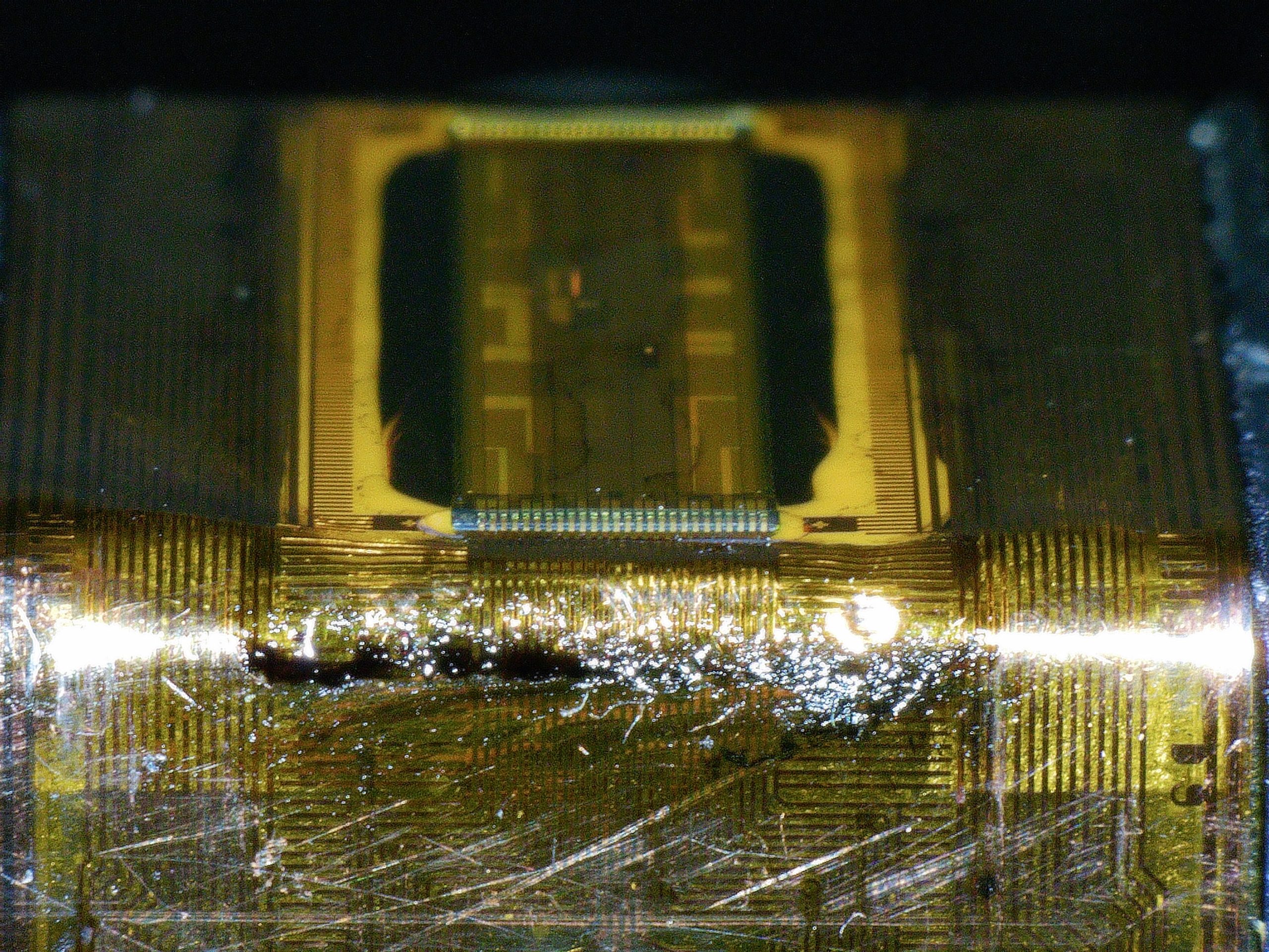
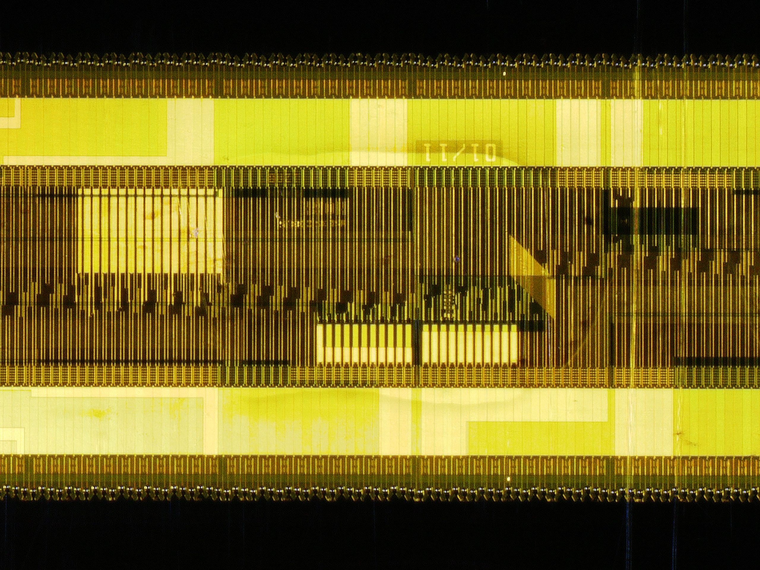
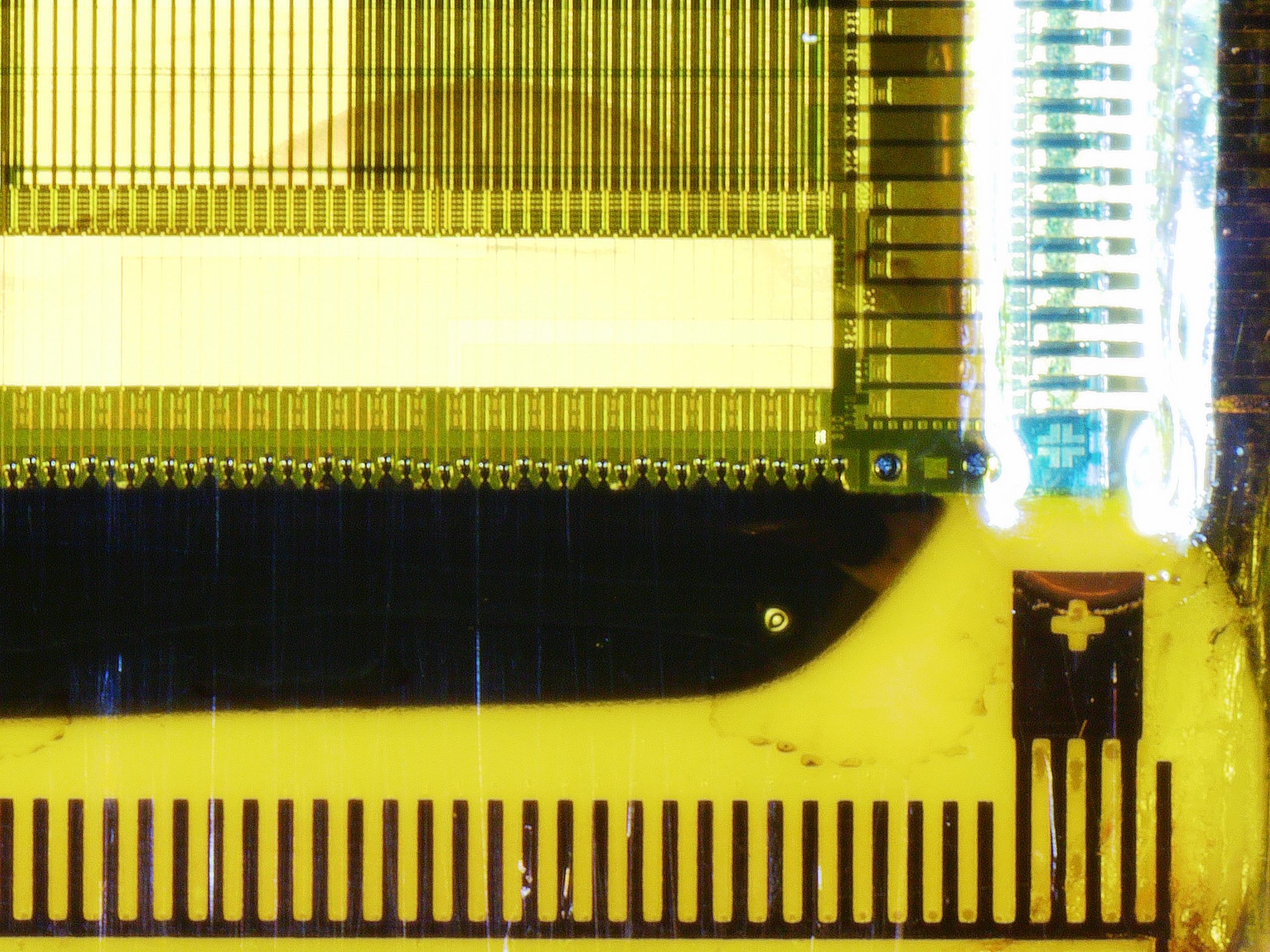
under the HP45 there are 300 nozzles, in 2 rows of 150. Each nozzle has a diameter of around 20-40 microns according to the patent (US5946012). In the closeups of the printhead there is a distinct rectangle surrounded on either side by black bars. The rectangle is the nozzle die. On both the top and the bottom are the contact which connect the PCB with the contacts to the die. The black bars on the left and right are the ink. The ink feeds the nozzles from the sides of the die.
The size of the drop of ink varies from ink to ink. By experimentation it was determined that 15.000.000 droplets of original ink weigh around 0.479 grams, making each droplet around 31.3 picogram. The same printhead printing 60% water, 40% isopropylalcohol prints with droplets of around 19.3 picogram.

Inside the printhead
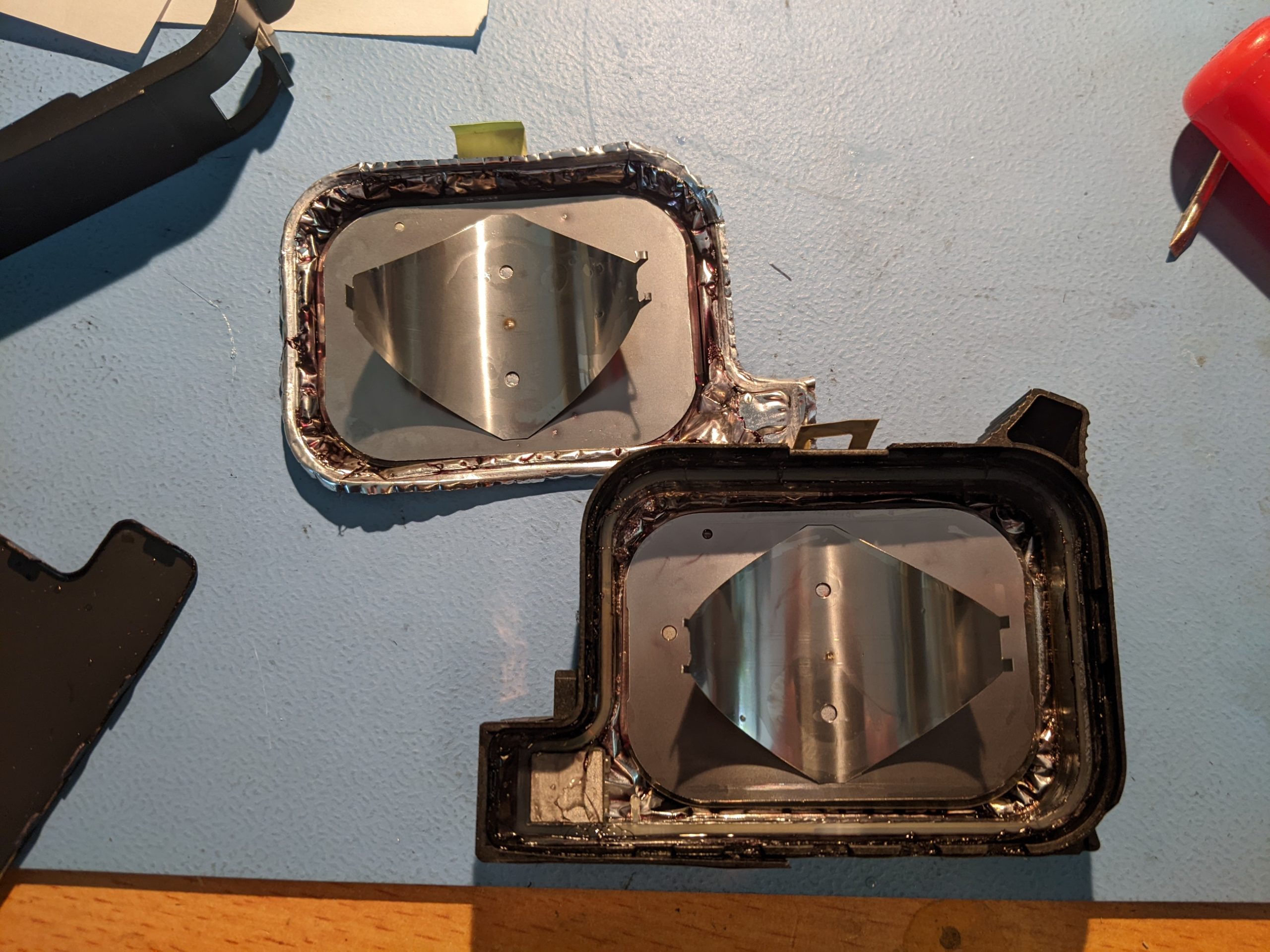
Ink tank
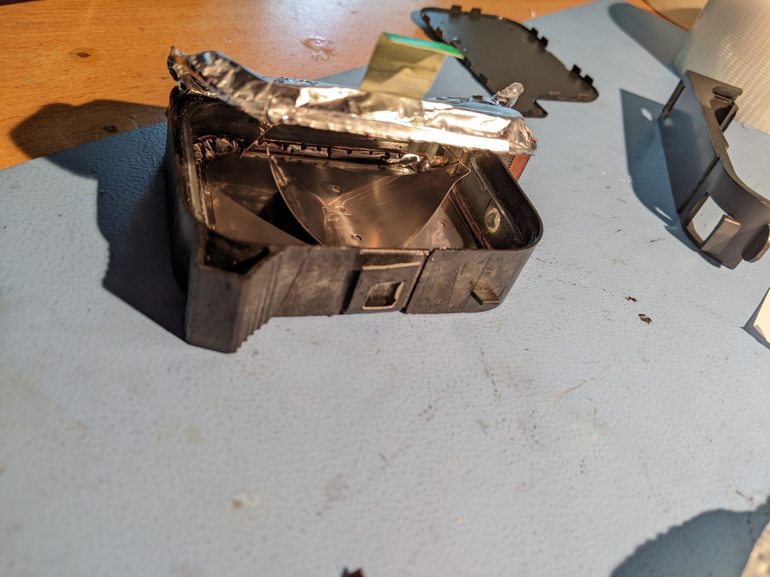
Removing the side reveals an aluminium bag that moves and springs back when you press it. This is the ink tank of the printhead. Opening the bag reveals what sits inside. A leaf spring is what presses the bag open. This spring is used to create a negative pressure on the printhead to keep the ink in the nozzles.
Around the entire edge of the printhead is a rubbery plastic rim to which the aluminium bag is sealed on either side. Removing the aluminium takes relatively little force. This is why the printhead cannot really be over-pressured. The printhead in the photo’s had the ink tank seal burst due to over-pressure while filling.
Inside the plastic rim on the bottom of the printhead is a hole. This is the fill port. A metal ball is pressed into this hole to seal the printhead. To refill the hole the ball is pressed inside the printhead. If you have a printhead that has been refilled several times you can hear all the balls that have been pressed in, rattling in the printhead if you shake it.

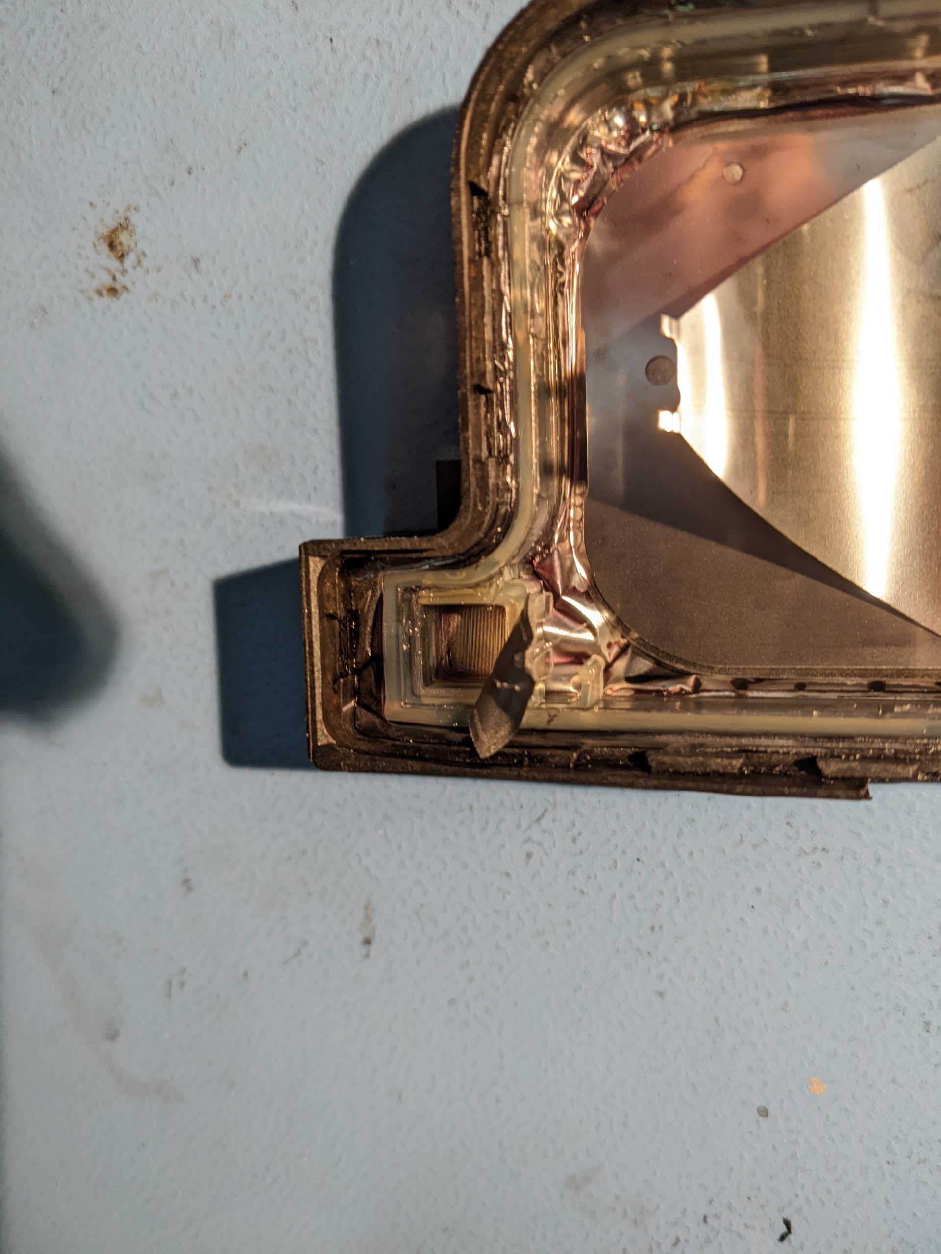
Nozzle filter and entry
Towards the nozzles is a mesh. This is the filter for the nozzles. Under the filter is a chamber and an eye shaped hole leading towards the nozzles. If you plan to make a CISS printhead, where the nozzles are supplied directly via a tube, this is where you want to attach this tube. Do be careful though not to get glue into the eye shaped hole, or risk getting glue in the nozzles.

Electronics
The contacts on the back of the printhead are on a piece of flexible PCB, which goes down to the die and makes contact there. On each side of the die there are 26 contacts, totaling 52.
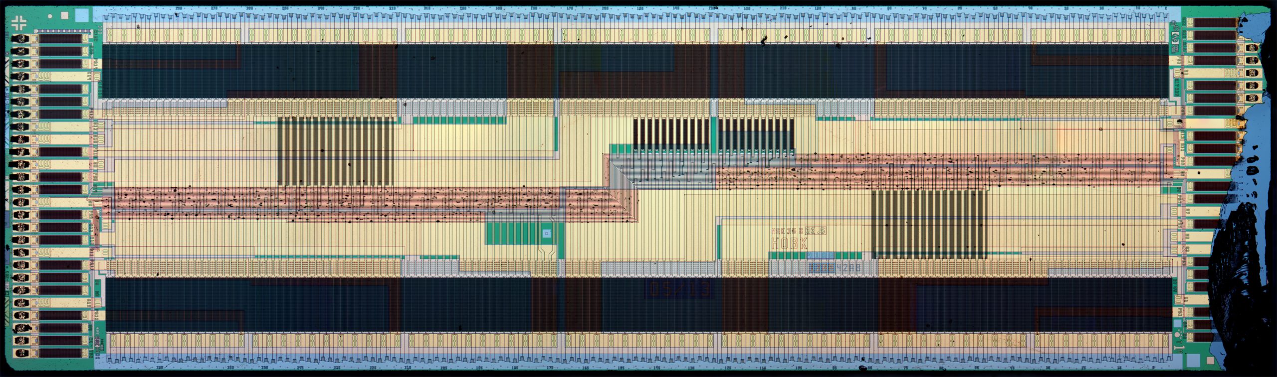
The die from the previous chapter holds more than only the nozzles, or the nozzle heaters. It contains the circuitry required to drive 300 nozzles without needing more than 300 contacts. This is done by multiplexing the nozzles, where they are fired in clusters called addresses and primitives.
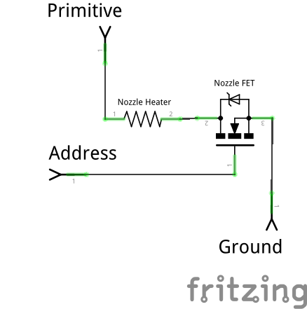
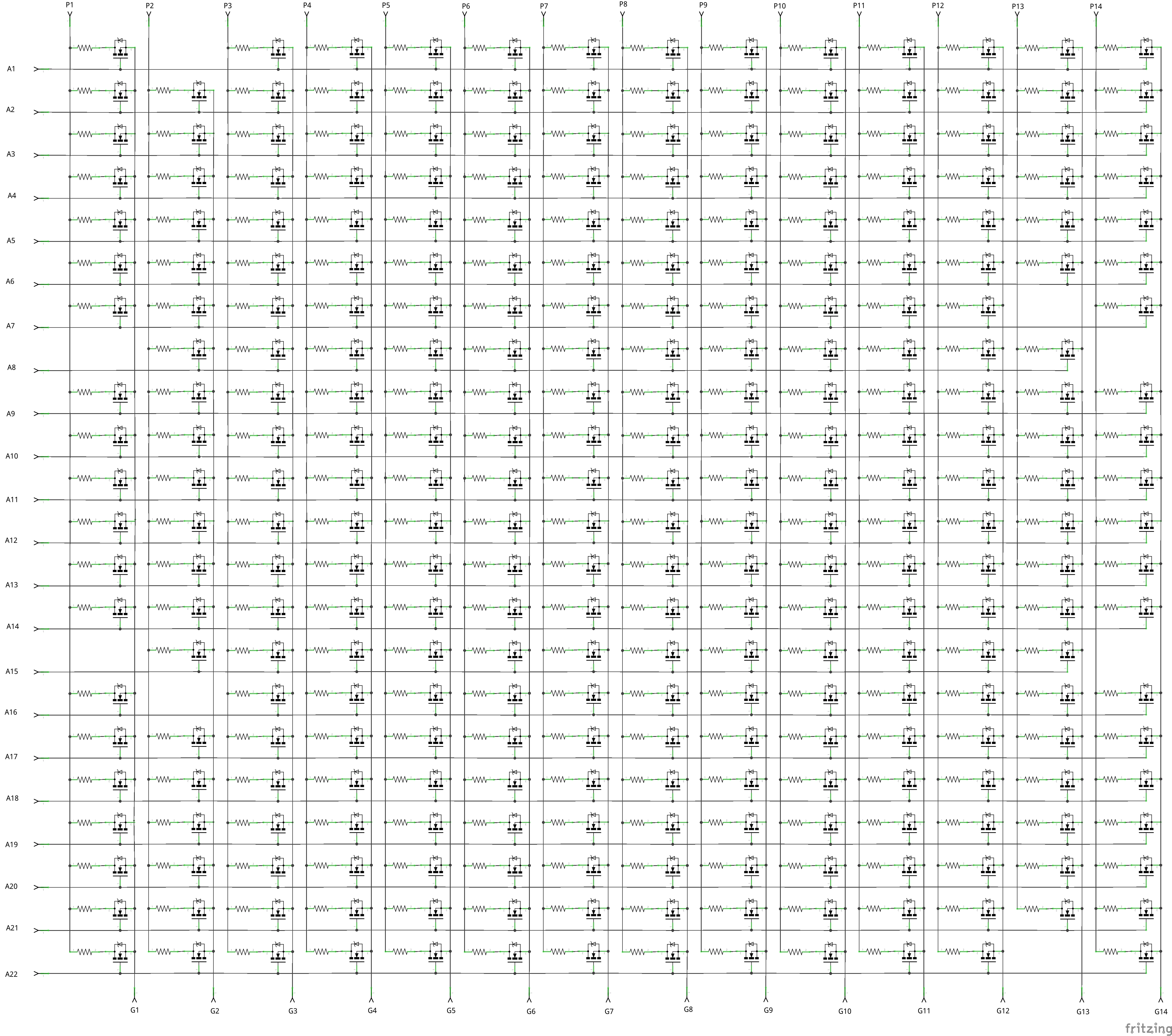
Each nozzle consists of a heater resistor and a FET. The address is attached to the gate of the FET, and opens the FET. The primitive is attached to the heater resistor, with the FET stopping the flow of electrons. Due to the limitations of the electronics on the die, the FET cannot be switched while there is power flowing through the nozzle. The primitive needs to be switched off before the address can change.
The TSR and 10X resistor sit somewhere on the die. The exact function is a bit unclear, but the 10X seems to be a reference (10x the nozzle resistance seems like a decent guess) and the TSR is a NTC resistor, allowing for a decent measurement of the printhead.
More details on how the nozzles work in an HP45 can be found here: https://ytec3d.com/hp45-inkjet-printhead/