The following page is a description of how the data is sent to the controller. to control every aspect of the controller. It contains an explanation of how the data is sent, stored, printed and a full list of commands. This list is meant for people who write their own software to control the printhead. Programs like inkjet commander use the structure and commands described on this page to control the controller and to send data.
Command structure
The serial connection uses a semi fixed command structure to send data to and from the HP45 controller. The serial port used is the hardware USB to serial converter within the microcontroller itself. The computer should see the Teensy 3.5 as a Serial port.
The data is sent in blocks of 64 bytes. The buffer is 64 bytes both ways. Each block consists of a semi fixed structure, that looks like this:
CCCC-PPPPP-[50xR]e
(CCCC-PPPPP-RRRRRRRRRRRRRRRRRRRRRRRRRRRRRRRRRRRRRRRRRRRRRRRRRRe)
- ‘-‘is a whitespace, to indicate an end of a line
- ‘C’ is a command. Each function has a 3 letter command
- ‘P’ is a small number, in inkjet reserved for position
- ‘R’ Raw data, in inkjet reserved for inkjet data
- ‘e’ end character (‘\r’ of ‘\n’) Based on context, some blocks can be different, but by default all value carrying blocks will be encoded in base 64
from 0 to 63: ABCDEFGHIJKLMNOPQRSTUVWXYZabcdefghijklmnopqrstuvwxyz0123456789+/
An example of a print line at position 53175 is: “SBR M+3 AAD///////////AAAAAAAAAAAAAAf//////////4AAD//////4″*
An example of set DPI to 600 is: “SDPI JY”*
(* end characters are not shown in the examples. From this point onward end character are not show in the commands)
The order of the data is always the same. The first value is always the command, the second value always the small value, and the third always the raw data. The Command is always required. Small numbers and Raw data may be skipped depending on the command. Which values are expected are mentioned in the details of each command.
The actual amount of characters per command or value can change, but a full line may not be more than 64 bytes including end characters. The command and values are case Sensitive.
Small numbers are encoded in base64, with the number counting the same way as in base10. In base10 numbers go 0 to 9, and than a 1 is added to count further with 10 to 19. In base64 Numbers 0 to 63 are ‘A’ to ‘/’. To go to 64, a ‘B’ is added to make ‘BA’. This process continues with higher numbers.
The numbers can have a sign. ‘Bk’ is 100, ‘-Bk’ is -100.
| Base10 | Base64 | Base10 | Base64 | Base10 | Base64 |
| 0 | A | 20 | U | 500 | H0 |
| 1 | B | 50 | y | 600 | JY |
| 2 | C | 75 | BL | 1.000 | Po |
| 3 | D | 90 | Ba | 1.200 | Sw |
| 4 | E | 100 | Bk | 1.500 | Xc |
| 5 | F | 110 | Bu | 2.000 | fQ |
| 6 | G | 120 | B4 | 3.000 | u4 |
| 7 | H | 150 | CW | 4.000 | +g |
| 8 | I | 200 | DI | 5.000 | BOI |
| 9 | J | 250 | D6 | 7.500 | B1M |
| 10 | K | 300 | Es | 10.000 | CcQ |
Command buffering
The printhead controller is capable of buffering a certain number of lines. This aids in printing larger images and prevents the user from having to deal with the 2 separate rows of nozzles. The HP45 V4 controller has a buffer of 4000 lines. This means that the HP45 V4 controller can store 4000 changes in what nozzles to use in an image. The order of the lines are as they are received. Multiple sweeps (movements in 1 direction containing an image) can be kept in the buffer.
Only lines that can be printed are buffered. This is all the functions in “Print commands”. All buffered commands are only executed after the right printing position is reached.
All other commands are executed when they are received. A Set DPI or Set Side will be executed as soon as it is received.
Warning: Make sure that you are not printing when changing settings. This can create faults in the printed image or create a situation where the printhead gets stuck in a state that requires the buffer to be cleared or the controller to be restarted.
Image data handling
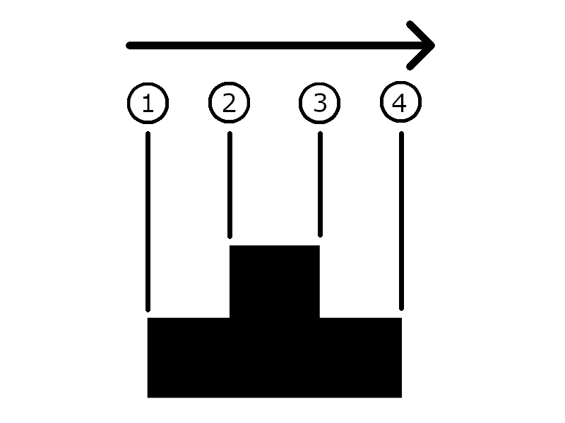
The image data is handled in changes. Instead of sending every line as the pixels that need to be printed, changes are communicated to the controller. The data is always sent with a positions in microns. If the change happens at the position 5mm, the data is sent with the coordinate 5000. The diagram below shows this as an example. The print happens from left to right. For the example assume that the whole image is 300 pixels tall.
- At position 1 is the first change. Here the half of the printhead is on, and the top row is off. Here the controller is told that the first 150 (0-149) nozzles are on. The next 150 nozzles (150 to 299) are off.
- At position 2 the image changes again. Now all nozzles (0-299) can be on.
- At position 3 the image changes to the same value as position 1. The first 150 (0-149) nozzles are on. The next 150 nozzles (150 to 299) are off.
- At position 4 the image turns off completely. All nozzles (0-299) are turned off.
The printhead handles most of the intelligence. It knows what nozzles 0-299, and it handles the fact that all nozzles are not actually in a neat single row, but in two rows 4mm apart. All the user needs to do is send the changes to the controller, with their corresponding positions. Direction is also an important thing to keep in mind. The controller always assumes that the line is printed from the current line of pixels, to the next one. If the next line of pixels on a coordinate higher than the current, the nozzles will only fire when moving in the positive direction. If the next line of pixels is at a lower position than the current position, the nozzles will only eject ink when moving in a negative direction.
Returns
Every line that is received by the controller is responded to with an ‘OK’. This notifies the user or software that the line was received and the data was processed. After an ‘OK’ is received the controller is ready to receive the next line.
Attention: Sending a line to the controller before an ‘OK’ is received might result in the data of that line being lost.
Any command that returns data always precedes that data with the command. This is done so the software can identify what the response is about. For instance, when asking for the temperature, a user can send: “GTP”. The system might respond with: “GTP D6”, signaling that the temperature is 20.0 degrees C.
Print commands
SBR: Send Buffer Raw
Send a print line to the buffer, to be printed when the correct position and direction is reached. The position is point at which this line starts to be active. The raw data is the up to 50 Base64 characters with either on (1) or off (0). Every 6 bits make 1 Base64 character. 000000 = A, 000001 = B and so forth.
Input: Small value: The position in microns where the given change needs to happen
Input: Raw Data: Up to 50 characters Base64 data, where each of the 6 bits in each character defines if the pixel needs to be on or off. Goes from LSB to MSB, 0-299.
Returns: Nothing
Print support
PHT: Preheat printhead
Sends short pulses to the printhead in order to heat it up.
Input: Small value: The number of heating cycles in Base64
Returns: Nothing
Attention: Preheat takes a significant amount of time (up to full seconds) to complete at larger values.
Attention: While preheat should not eject ink, it cannot be guaranteed that it will not.
Warning: Do not use values too large (>25.000) as it might heat the head up too much.
PRM: Prime printhead
Sends long pulses to the printhead in order to eject ink.
Input: Small value: The number of priming cycles in Base64
Returns: Nothing
Attention: Prime takes a significant amount of time (up to full seconds) to complete at larger values.
Attention: Prime will eject ink. Do not use this command in places where no ink should go.
THD: Test Head
GTP: Get Temperature
Measures the temperature of the printhead and returns it.
Input: Nothing
Returns: The temperature in Base64 in 0.1 degrees Celcius. ‘D6’ is 250, which means 25.0 degrees Celsius. Can also return a -2. This means that one of the measurements of the test was out of bounds. This usually happens when the printhead is not connected.
SDP: Set DPI
Sets the resolution of the data to the printhead. At the native resolution of 600DPI the swatch size is 300 pixels. At 300DPI every pixel sent is printed with 2 nozzles. This limits the swatch size to 150 nozzles. At 200DPI every pixel sent is printed by 3 nozzles, making the swatch size 100. Does not alter the physical resolution. All 300 nozzles are still used for printing.
Input: Small value: The resolution to be printed in Base64. Only allowed values are 600 (‘JY’), 300 (‘Es’), 200 (‘DI’), 150 (‘CW’), 100 (‘Bk’) and 75 (‘BL’).
Returns: Nothing
Example: “SDP JY” Sets the resolution to 600DPI
Default: 600DPI.
SDPI: Set DPI
A copy of the “SDP” command.
Input: Small value: The resolution to be printed in Base64. Only allowed values are 600 (‘JY’), 300 (‘Es’), 200 (‘DI’), 150 (‘CW’), 100 (‘Bk’) and 75 (‘BL’).
Returns: Nothing
Example: “SDPI JY” Sets the resolution to 600DPI
Default: 600DPI
SDN: Set Density
Sets the density at which the ink is deposited. Native density (100%) is 600 shots per nozzle for every inch moved. At higher density more shots are made per inch (900 at 150%) and at a lower density fewer shots are made per inch (450 at 75%).
Input: Small value: The desired density of the print as a percentage in Base64.
Returns: Nothing
Example: “SDN Bk” Sets the print density to 100%
Default: 100%
SSID: Set Side
Sets the sides of the printhead that print. The HP45 has 2 rows of nozzles 4mm apart. In some printing conditions it is undesirable to print with both.
Input: Small value: The side(s) to print with. ‘A’ (0) is both sides, ‘B’ (1) is odd, and ‘C’ (2) is even.
Returns: Nothing
Default: Both sides (‘A’)
SPSP: Set Pulse Split
Sets the number of firings required for each pulse of the printhead. Due to thermal and electrical limitation the printhead cannot always fire all the primitives on an address at once. The controller can split the firing up into ‘splits’ to make sure all nozzles fire cleanly.
Input: Small value: The number of splits for each address. Allowed values are 1 (‘B’), 2 (‘C’), 3 (‘D’), and 4 (‘E’)
Returns: Nothing
Default: 3 splits (‘D’)
GPSP: Get Pulse Split
Get the number of splits currently active on the controller. For a description of pulse splits see “SPSP”.
Input: Nothing
Returns: The current pulse split value in Base64
Buffer
BMOD: Buffer Mode
Buffer mode sets the behaviour of the buffer.
- Clearing (Mode 0 or A): Removes the print line from the buffer after it is printed, creating space for new print lines to be added.
- Static (Mode 1 or B): Retains the line after it is printed. Any image to be printed needs to fit in the full buffer.
- Looping (Mode 2 or C): Retains the data in the buffer and automatically jumps back to the first print line after the last print line was printed
Input: Small Value: The mode in Base64
Returns: Nothing
BRL: Buffer Read Left
Get the amount of lines that can be read from the buffer
Input: Nothing
Returns: The amount of lines that can be read from the buffer in Base64
BWL: Buffer Write Left
Get the amount of lines that can be written to the buffer.
Input: Nothing
Returns: The amount of lines that can be written to the buffer in Base64
BCL: Buffer Clear
Removes all data from the buffer and resets buffer to zero.
Input: Nothing
Returns: Nothing
BRES: Buffer Reset
Resets the buffer to line 0. This effectively allows the user to reprint the same image if it was not cleared.
Input: Nothing
Returns: Nothing
Attention: BRES reliability cannot be guaranteed in buffer mode ‘Clearing’.
Position mode
SPME: Set Position Mode Encoder
Sets the controller to use the encoder as the input for printing. This mode takes the encoder signal on CHA and CHB and converts it to a position.
Input: Nothing
Returns: Nothing
SPMV: Set Position Mode Virtual
Sets the controller to use a virtual position as the input for printing. In virtual mode a given speed and position are used. A trigger determines when the movement started. The controller will then calculate the position based on starting time, starting position and velocity.
Input: Nothing
Returns: Nothing
SEP: Set Encoder Position
Set the encoder position to a given value.
Input: Small value: The current position in Base64 in microns. Is allowed to be negative.
Returns: Nothing
Example: “SEP u4” Sets the encoder position to 3000 microns, or 3mm.
GEP: Get Encoder Position
Gets the current encoder position.
Input: Nothing
Returns: The current encoder position in Base64. The value can be negative.
Example: “GEP” can return “GEP:-u4”, which means the current encoder position is -3000 microns, or -3mm.
SER: Set Encoder Resolution
Sets the number of encoder pulses for a movement of 25.4mm (1 inch).
Input: Small value: The number of pulses per inch in Base64. Number can be negative.
Returns: Nothing
Example: “SER JY” Sets the encoder resolution to 600 pulses per inch.
Attention: The value the controller needs is the x4 pulses per inch. In most cases this is 4 times as much as the given PPI value.
GER: Get Encoder Resolution
Respond with the current encoder pulses per movement of 25.4mm (1 inch) value.
Input: Nothing
Returns: The current pulses per inch value in Base64.
Example: Sending “GER” to the controller can give a response “GER:JY”, which is 600 pulses per inch.
VENA: Virtual Enable
Can enable and disable the virtual motion. When disabled, the virtual movement will not continue to run and will not respond to triggers.
Input: Small Value: Disable virtual movement (‘A’) or enable virtual movement (‘B’)
Returns: Nothing
Attention: Disabling virtual motion will stop the movement. Enabling it will enable the movement from the position where it was disabled.
GVP: Get Virtual Position
Get the current Virtual position
Input: Nothing
Returns: The current virtual position in microns in Base64.
Example: “GVP” can return “GVP:-CcQ”, which means the current virtual position is -10.000 microns, or -10mm.
SVV: Set Virtual Velocity
Set the virtual velocity. The virtual velocity is the speed at which the virtual position moved when virtual movement is enabled and movement has been triggered. Velocity can be negative.
Input: Small Value: The desired velocity in millimeters per second in Base64.
Returns: Nothing
Example: “SVV y” Sets the virtual velocity to 50mm/s
GVV: Get Virtual Velocity
Gets the current set virtual velocity. The virtual velocity is the speed at which the virtual position moved when virtual movement is enabled and movement has been triggered.
Input: Nothing
Returns: The current virtual velocity in millimeters per second in Base64.
Example: “GVV” can return “GVP:-y”, meaning that the current virtual velocity is -50mm/s.
SVR: Set Virtual position Reset
Sets the position that virtual position moves to when a trigger occurs. After a trigger happens, movement can start and starts at the given position.
Input: Small Value: The reset position in microns in Base64.
Returns: Nothing
Example: “SVR BOI” sets the reset position to 5000 microns, or 5mm. After a trigger the position will now start at 5mm.
Trigger mode
VRTI: Virtual Trigger
Acts as a trigger to starts what should happen when a trigger happens.
Inputs: Nothing
Returns: Nothing
VSTO: Virtual Stop
Stops the virtual movement
Inputs: Nothing
Returns: Nothing
STM#: Set Trigger Mode [port number]
Set what mode triggers the trigger. # is replaced with the number of the port. The first trigger pin ‘STM0’, the second trigger pin is ‘STM1’ and so forth.
On the HP45 controller the order for the trigger pins from 0 to 8 is: Ex1, Ex2, Ex3, Ch_A, Ch_B, Rx, Tx, SDA, SCL.
Inputs: Small value: The trigger mode for the given pin. 0 (‘A’) for off, 1 (‘B’) for rising edge, 2 (‘C’) for falling edge, 3 (‘D’) for on toggle.
Returns: Nothing
STR#: Set Trigger Resistor [port number]
Set the internal resistor for the given triggers pin. # is replaced with the number of the port. The first trigger pin ‘STR0’, the second trigger pin is ‘STR1’ and so forth.
On the HP45 controller the order for the trigger pins from 0 to 8 is: Ex1, Ex2, Ex3, Ch_A, Ch_B, Rx, Tx, SDA, SCL.
Inputs: Small value: The trigger mode for the given resistor type. 0 (‘A’) for floating, 2 (‘C’) for Pull-up and 3 (‘D’) for pull-down.
Returns: Nothing
Attention: The Arduino scheme for internal resistors is used, so the missing 1 is not a mistake in the list above. Mode 1 is output. The firmware prevents 1 from being used.
Warning: Some pins are expected to have certain internal resistors. If an encoder is used, this requires a pull-down. Setting the resistor on a pin already in use might render the given pin inoperable.
Direct control
!WPR: Write Pin Raw
Directly sets a pin to the given value. Allowed pins to set directly are:
- ARS: Address reset
- ACL: Address clock
- P00: Primitive 0
- P01: Primitive 1
- P02: Primitive 2
- P03: Primitive 3
- P04: Primitive 4
- P05: Primitive 5
- P06: Primitive 6
- P07: Primitive 7
- P08: Primitive 8
- P09: Primitive 9
- P10: Primitive 10
- P11: Primitive 11
- P12: Primitive 12
- P13: Primitive 13
- PCL: Primitive Clock
- ENA: Head enable
Inputs: The 3 letter pin name, followed by an ‘A’ (off) or a ‘B’ (on) without spaces.
Returns: Nothing
Example: “!WPR ENAB” will make the enable pin high.
Attention: While the controller is running normally, it might still alter the state of some pins. Even with inkjet mode turned off. This function is for debugging only.
Warning: directly setting the wrong pin can damage the controller. Only use this function for debugging if you know what the risks of setting it are.
!INM: Inkjet Mode
Controls the inkjet code of the controller. Allows the code that handles inkjet to be enabled or disabled. Disabling the inkjet allows for troubleshooting without the normal printing functions controlling pins at inopportune times.
Inputs: Small value: Inkjet mode on (1 or ‘B’) or Inkjet mode off (0 or ‘A’).
Returns: Nothing
Default: Inkjet mode On
Attention: Setting Inkjet mode to 0 will stop all inkjet related actions. It will stop the update of the Buffer, and the printing commands. It will not stop other functions line position, serial reading, triggers and debugging.
Status calls
GWAR: Get Warnings
Get the current warnings of the controller. Warnings are problems that can still be printed with. The following bits correspond to the following warnings:
- 0: Head temperature high (more than 45C)
Input: Nothing
Returns: A value in B64, where each bit corresponds to a given warning.
Example: “GWAR” might return “GWAR:B”, which is means that the head temperature is high.
GERR: Get Errors
Get the current errors of the controller. Errors will not allow the controller to print anymore. If the response from ‘GERR’ is anything other than 0, the controller will not be printing anymore. The following bits correspond to the following errors:
- 0: Logic voltage low (logic voltage lower than 11V)
- 1: Logic voltage high (logic voltage higher than 13V)
- 2: Driving voltage low (Driving voltage lower than 7V)
- 3: Driving voltage high (Driving voltage higher than 15V)
- 4: Head temperature NC (Printhead not connected)
- 5: Head temperature high (temperature higher than 60C)
- 6: Address defective (address did not pass self testing)
- 7: Dummy1 not rising (Dummy1 voltage did not rise during self testing)
- 8: Dummy1 not falling (Dummy1 voltage did not fall during self testing)
- 9: Dummy 2 not rising (Dummy2 voltage did not rise during self testing)
- 10: Dummy2 not falling (Dummy2 voltage did not fall during self testing)
Input: Nothing
Returns: A value in B64, where each bit corresponds to a given error.
Example: “GERR” might return “GERR:V”, which is 21, or , 10101. This is bit 0, 2 and 4 high. This means that the voltage for both address and driving voltage rail is low, and the head is not connected.
Debug
#COM: Command Echo
Makes the controller respond with the decoded value of the command. Used to help add new commands to the controller.
Input: Small value: Command echo off (‘A’) or on (‘B’).
Returns: Nothing
Example: With command echo enabled, the controller will respond to “#COM” with “COM:591613773”. This is also the value in the firmware attached to the “#COM” command.
#NDS: Number Decode Small
Takes an input and decodes the Base64 value to Base10.
Input: Small value: Any number to be decoded in Base64.
Returns: The decoded value in Base10.
Example: “#NDS fQ” Returns “#NDS:2000”.
#NDR: Number Decode Raw
Takes raw data in Base64 and decodes it to a list of Base10 values.
Input: Small Value: Any small value number in Base64.
Input: Raw data: Up to 50 characters in Base64.
Returns: A list of Base10 numbers corresponding to the numbers in the raw data, separated by spaces.
Example: Sending “NDR fQ //rGh//” returns “NDR:0 0 0 0 0 0 0 0 0 0 0 0 0 0 0 0 0 0 0 0 0 0 0 0 0 0 0 0 0 0 0 0 0 0 0 0 0 0 0 0 0 0 0 63 63 43 6 33 63 63”. The numbers match the Base64 value of the raw data.
Attention: ‘#NDR’ will always decode 50 numbers. If it cannot find 50 numbers, it will add zeros until it is at 50.
#NES: Number Encode Small
Encode a number from Base10 to Base64. It is a small value in Base10 and responds with the Base64 value. #NES is an exception in that it practically takes a Base10 as an input.
Input: Small value: The to be decoded number in Base10
Returns: The input number converted in base64
Example: “#NES 150” responds with “#NES: CW”
Attention: #NES only responds with up to 2 characters. Any number larger than 4096 only shows the 2 least significant bits
#DEB: Debug Mode
In debug mode many functions will write their values to serial. This can be used to debug some of the functions. Especially the Serial decoding has a lot of information in Debug mode.
Input: Small value: The debug mode in Base64. ‘A’ is off, ‘B’ is All, ‘C’ is Serial only.
Returns: Nothing
Attention: Enabling debug mode is for debugging only (obviously). The data provided is human readable and not for use in any automated process. The Data is subject to change as features get added to the firmware.
#CYC: Set Cycle Counter
Enable or disable the cycle counter. The cycle counter will give a message every second with the number of cycles the code has made that second. Higher is better, and a minimum of around 10.000 is expected to run the controller properly.
Input: Small Value: ‘A’ for disable the cycle counter, ‘B’ for enable the cycle counter.
Returns: Nothing
Example: The cycle counter is enabled with “#CYC B”. The cycle counter does not have a formal response. It does push a message every second. The message can look as follows: “Cycles p/s: 80577” where the number is the number of cycles performed in the last second. In this case 80577 cycles per second.
Attention: The cycle counter does impact performance slightly. It is not advised to have it running during printing. Also since the counter does impact performance, the real number of cycles per second might be slightly higher.