Inkjet commander is a program used to control the HP45 controller. It can be used to alter all settings and send images to the printhead. It is currently not capable of actually driving motion, or printing anything other than bitmap images. More features will be added in the future to remedy this.
download link
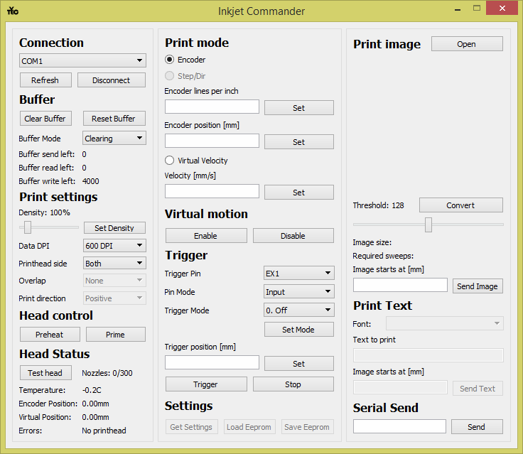
The interface of inkjet commander is split into several category. Each category is shown in the diagram below.
- Connection
- Buffer
- Print settings
- Head control
- Head status
- Print mode
- Virtual motion
- Trigger
Settings(not yet implemented)- Print image
Print text(not yet implemented)- Serial Send
A full explanation is given for each function in each category below.
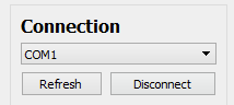
Connection
Connection handles establishing a link with the HP45 controller.
- The drop down menu lists all available ports. When you plug the Teensy in, the computer will assign a port to the Teensy. On windows the devices can be found in the device manager. Select the port of the HP45 controller.
- “Refresh” updates the list of com ports. When you plug in the controller after the software has started you may need to see the correct port.
- “Connect”/”Disconnect” starts and breaks the link with the HP45 controller. The text on the button is the action that will happen when you press it. Connect will start the connection, disconnect will stop it.
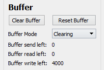
Buffer
Buffer has all the values and functions regarding the print buffer. The print buffer is where the lines to be printed are stored until they need to be printed.
- “Clear Buffer” will remove all data from the buffer and reset it to zero.
- “Reset Buffer” will keep all the data, and set the print position to 0 (does not work in clearing mode).
- “Buffer Mode” determines what the controller does with the data when it has printed it.
- “Clearing” removes the lines from the buffer after printing
- “Static” does not remove the data from the buffer when it has been printed
- “Looping” automatically resets the buffer after the last line has been printed
- “Buffer send left” is how many lines are still held by inkjet commander that need to be sent to the controller.
- “Buffer read left” is how many lines can still be printed by the controller.
- “Buffer write left” is how many lines can still be written to the controller.
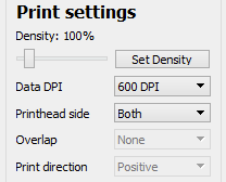
Print settings
Print settings has all the settings that impact how the image is printed.
- Density determined how many droplets are deposited per inch per nozzle. 100% is 600 droplets, 50% is 300 droplets.
- The slider determines the density. The text above will show what the current density is.
- “Set Density” actually write the density to the controller.
- “Data DPI” determines the resolution of the sent image. At 600 DPI every pixel sent is printed by one nozzle. At 300 DPI every pixel sent is printed by two nozzles and so forth down to 75 DPI. The drop down selects and writes the DPI to the controller.
- “Printhead side” determine what side of the printhead is used. “Both” uses both odd and even, “Odd” only prints with the odd side, and “Even” only prints with the even side.
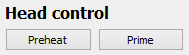
Head control
Head control can be used to send commands directly to the printhead.
- “Preheat” will send (mostly) non firing pulses to the printhead, warming it up.
- “Prime” will send firing pulses to the printhead to eject ink from all nozzles.
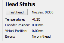
Head status
Head status shows all relevant data regarding the printhead and the controller.
- “Test head” makes the controller do a full diagnostic of the controller hardware and the printhead. The amount of working nozzles is shown besides the button. Pressing “Test head” will update this value. Any other errors will be shown in “Errors”
- “Temperature” shows the current printhead temperature. Printing will warm up the printhead.
- -0.2 is actually an error code that means no printhead is installed.
- “Encoder Position” Is the current position given by the encoder attached to the controller.
- “Virtual Position” Is the current virtual position of the printhead
- “Errors” Shows all errors and warnings currently experienced by the printhead. Errors can include:
- No printhead: no printhead installed
- 12V Bus low: 12V power missing
- Vhead Bus low: Printhead power (VHD) missing
- Head temp too high: printhead too hot
- Adrs not working: Address circuit did not pass self test
- Dummy1/Dummy2 not rising/falling: Primitive circuit did not pass self test
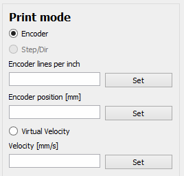
Print mode
Print mode enables selection of what movement is used to print. You can select the mode by clicking the item in the list.
- “Encoder” uses a quadrature signal from the Encoder port to determine the position.
- “Virtual Velocity” will use predefined speeds, set points and starting signals to calculate the position.
In each mode there are several settings that can be changed.
- “Encoder lines per inch” is the number of pulses from the encoder to move an inch. This is x4, so the number you put in might be 4 times bigger than pulses per inch calculated. Any integer number (positive or negative) is accepted. “Set” writes the value to the controller.
- “Encoder position [mm]” is the current position of the encoder. Any integer (positive or negative) millimeter value is accepted. “Set” writes the value to the controller.
- “Velocity [mm/s]” is the velocity that is used to calculate the virtual position. It may be any integer (positive or negative) millimeter per second value. “Set” writes the value to the controller.
Virtual motion
Once virtual motion itself is selected, it is by default disabled. You can manually enable or disable the virtual motion by pressing the “Enable” and “Disable” button. If you disable the virtual motion while it is moving, the movement will stop. Enabling it again will start the movement from where it was when you disabled it.

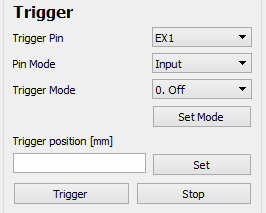
Trigger
A trigger is a hardware or software signal that sets a position to the active motion, starts virtual movement and resets the buffer depending on the mode. It can happen either through a software command or through a trigger pin.
- “Trigger Pin” selects the pin that the following settings will apply to. The names match the names on the HP45 V4 controller board.
- “Pin Mode” sets the resistor of the given pin.
- “Input” leaves the pin floating.
- “Input Pull-up” attaches a pull-up resistor to the input pin.
- “Input Pull-down” attaches a pull-up resistor to the pin.
- “Trigger mode” sets the condition the pin triggers at.
- “0. Off” sets the pin as not being a trigger.
- “1. Rising edge” Triggers on a rising edge.
- “2. Falling edge” Triggers on a falling edge.
- “3. Toggle” Triggers on a state change of a pin.
- “4. While high” is not yet implemented.
- “5. While low” is not yet implemented.
- “Set mode” writes all the properties given above to the pin selected.
- “Trigger position [mm]” Is the position the active motion will move to when a trigger is applied. This can be any integer positive or negative in millimeters. “Set” writes the value to the controller.
- “Trigger” will give a software trigger, starting all functions associated with a trigger.
- “Stop” will stop virtual movement.
Print image
In print image the image to be printed is selected and processed. It handles everything from opening to sending the image to the controller. The whole image, ink and no ink is sent to the controller. An image with large boundaries that are not printed are still sent to the controller.
- “Open” opens an image. This image can be jpg or png.
- Below the “Open” button a preview will appear. This is the raw input image. If the image is larger than 300×300 pixels it will be scaled.
- “Convert” will process the image for printing. It will take the threshold value and compare every pixel to it. If the pixel is darker than the threshold, ink will be deposited there. “Convert” may take a while depending on the size of the image.
- The slider determines the threshold value. The current threshold is shown above the slider. Lower means less of the image are printed. Higher means more of the image is printed.
- Below the slider information of the to be printed image is shown.
- “Image size:” shows the current size in pixels by pixels.
- “Required sweeps:” show the number of sweeps (passes of the printhead” are required to print the complete image.
- “Image starts at [mm]” Is the position where the first pixel of the image starts. The text box is used to enter any whole integer value (positive or negative) in millimeters.
- “Send Image” sends the image to the controller at the given position. If no position is given the position defaults to 10mm.

Serial Send
Allows the user the directly send data to the controller.
- The text area can be typed. The data typed here is one to one sent to the controller. The required end character are added automatically and do not need to be included.
- “Send” Sends the data to the controller and clears the text area.
