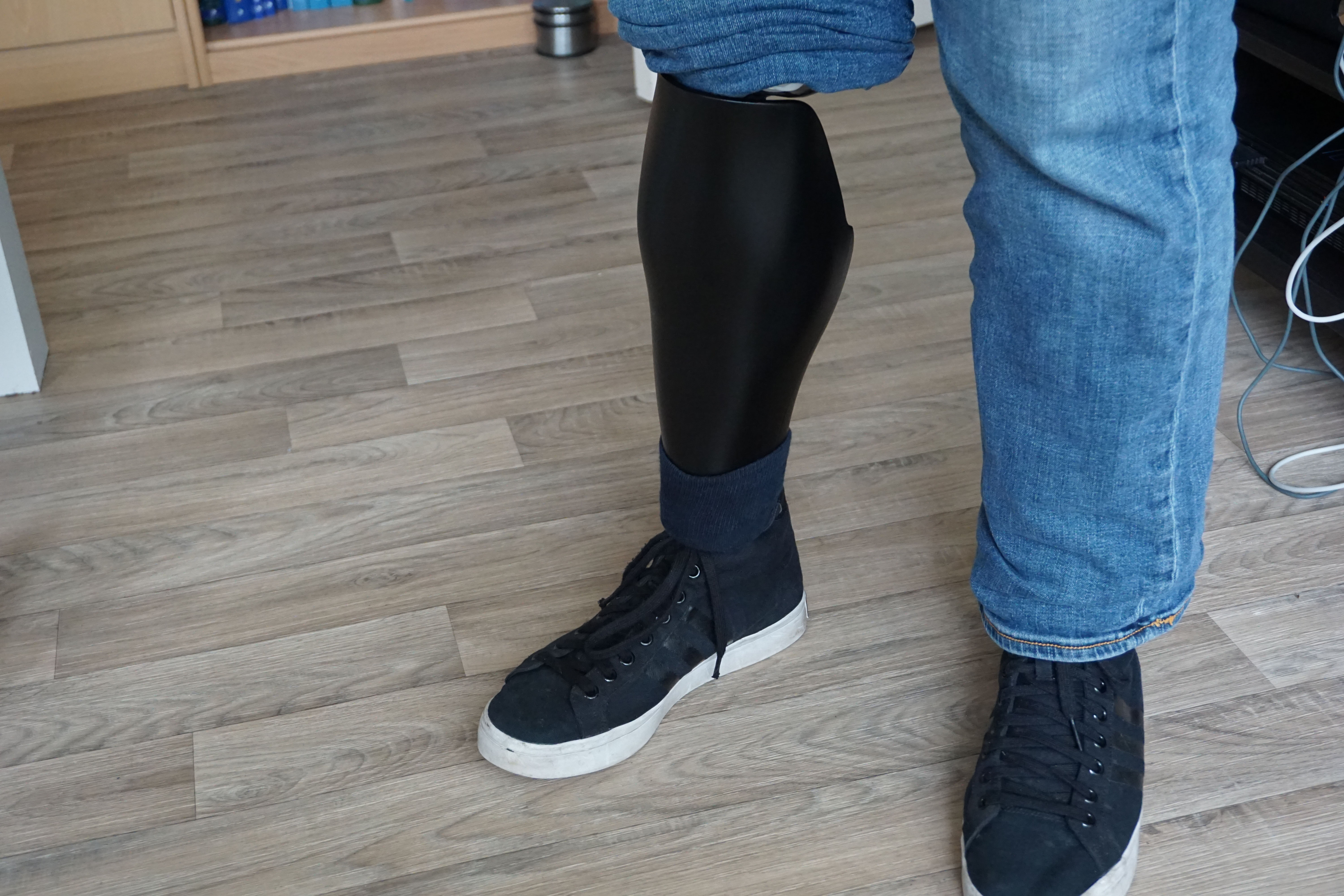
A while ago I was approached by a man with a leg prosthetic who wanted me to make a fairing. I had offered this on a message board a long time ago, but for over a year I got no reply. I decided to help. I had offered it. What followed was a 10 month development process. On this page I will give the story, with details on how and why. Unlike some of my other project, I will not share a final file and instructions for one to make, but I will give insight in design considerations and pitfalls I encountered along the way. I hope that when you have reached the bottom, you also will have an idea on how to design and make a fairing.
But first of, what is a fairing. Simply put, a fairing is a cover for a prosthetic to hide the mechanics. Most prosthetics are produced in larger series and don’t have a particularly natural (or nice) look. They are designed to be adjusted for many people, and usually look like a piece of colored plastic with a tube sticking out of it. While some people are fine with this, other prefer to have the prosthetic covered with something that is shaped a bit more like an actual limb. This is where the fairing comes in. Fairings are sold by plenty of companies and come in many shaped and size, ranging from natural looking plain covers to tiny works of art. One thing all fairings have in common is that they are expensive. They are mostly bespoke and fairly spendy. (for example images just google “prosthetic fairing”)
Beginning of the process
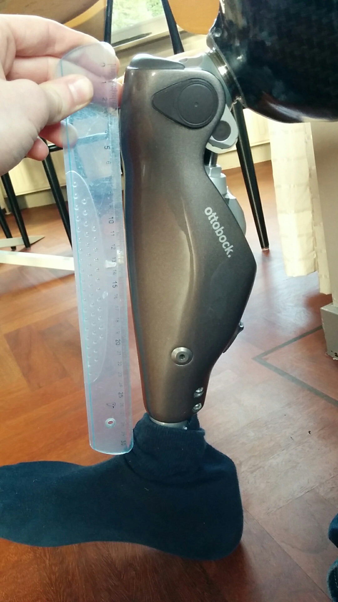
I started the project with a 3D scan of the opposite leg, a few reference photo’s of the prosthetic (with ruler) and a rough idea of what to make. This was going to be a plain shell in the shape of a leg to cover the prosthetic. Nothing fancy with materials and patterns. The prosthetic is for a amputation on the knee. The prosthetic does contain a knee, but it is further down than a knee would normally be. This means that to give the knee the same freedom, the knee has to bend further. For tools I used a Solidworks, a little bit of Maya, and Slic3r (yes, Slic3r for design) to design the fairing. Solidworks generally is not suited for organic shapes, but considering that I know this CAD package inside out, it was the best thing I had that I could work with. For a 3D printer I used a Gen 1 custom Ultimaker.
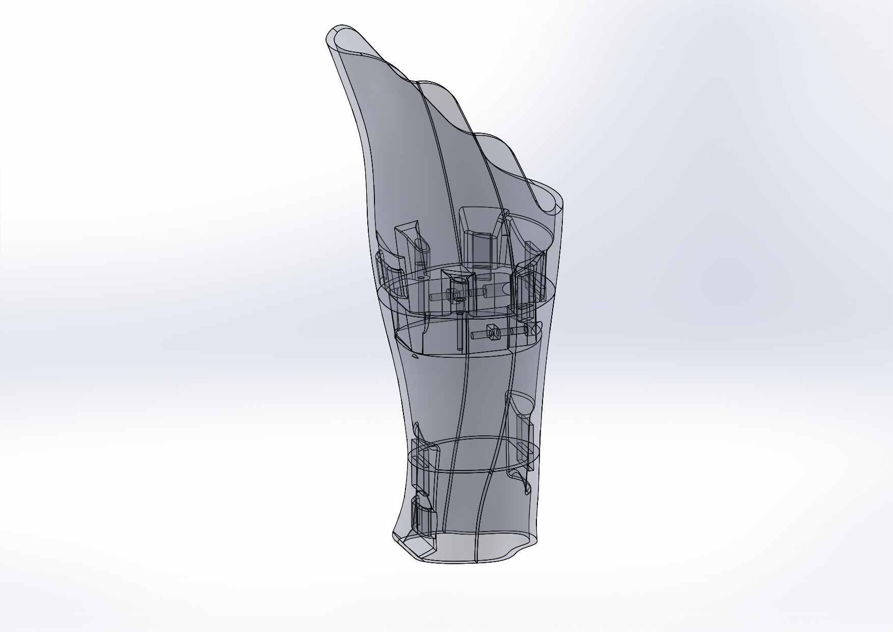
The basic idea was to make a fitting shell around the prosthetic. It consists of 2 shell halves. A front halve and a back halve. The front halve is mounted to the fairing (originally using Velcro). The back halve is then mounted to the front using screw, securing the fairing to the prosthetic. Inside the front halve of the fairing are 2 loops where Velcro can be hooked behind. 2 Allen key screws are used to mount the back half to the front halve. Inside the front halve are 2 self locking nuts, glued in place.
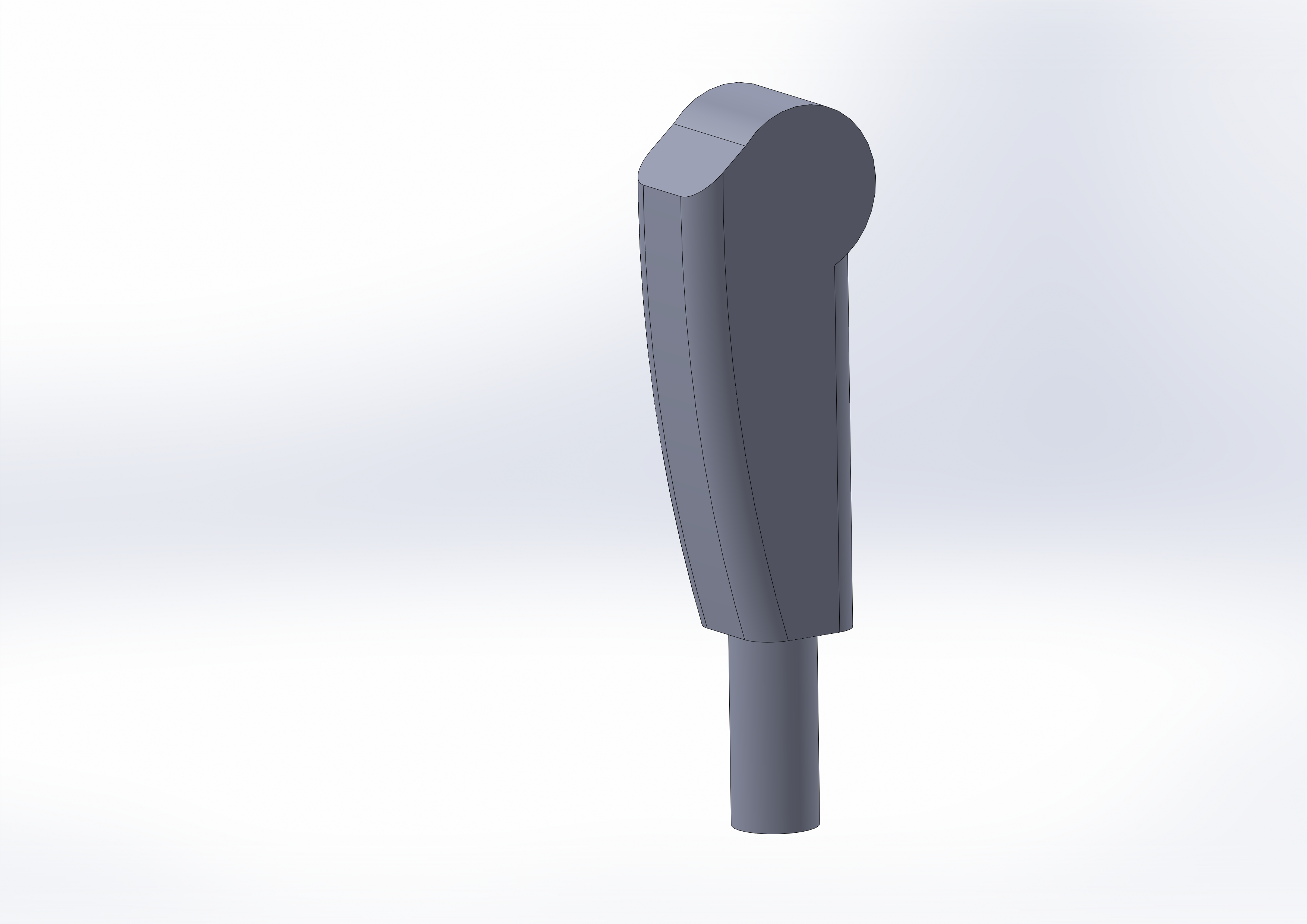
The first job was to get the prosthetic itself into Solidworks. Throughout the project, several different prosthetics will be seen. This is because the project took so long that the prosthetic was replaced. For reference I had several images with a ruler in place, plus some measurement I made myself. Using these, it should be fairly simple to get a decent model in Solidworks (right?).
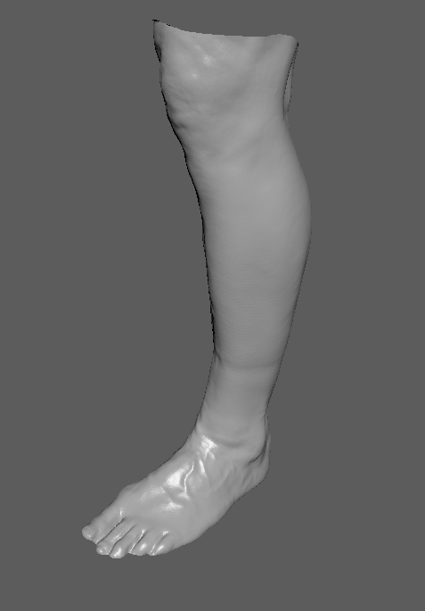
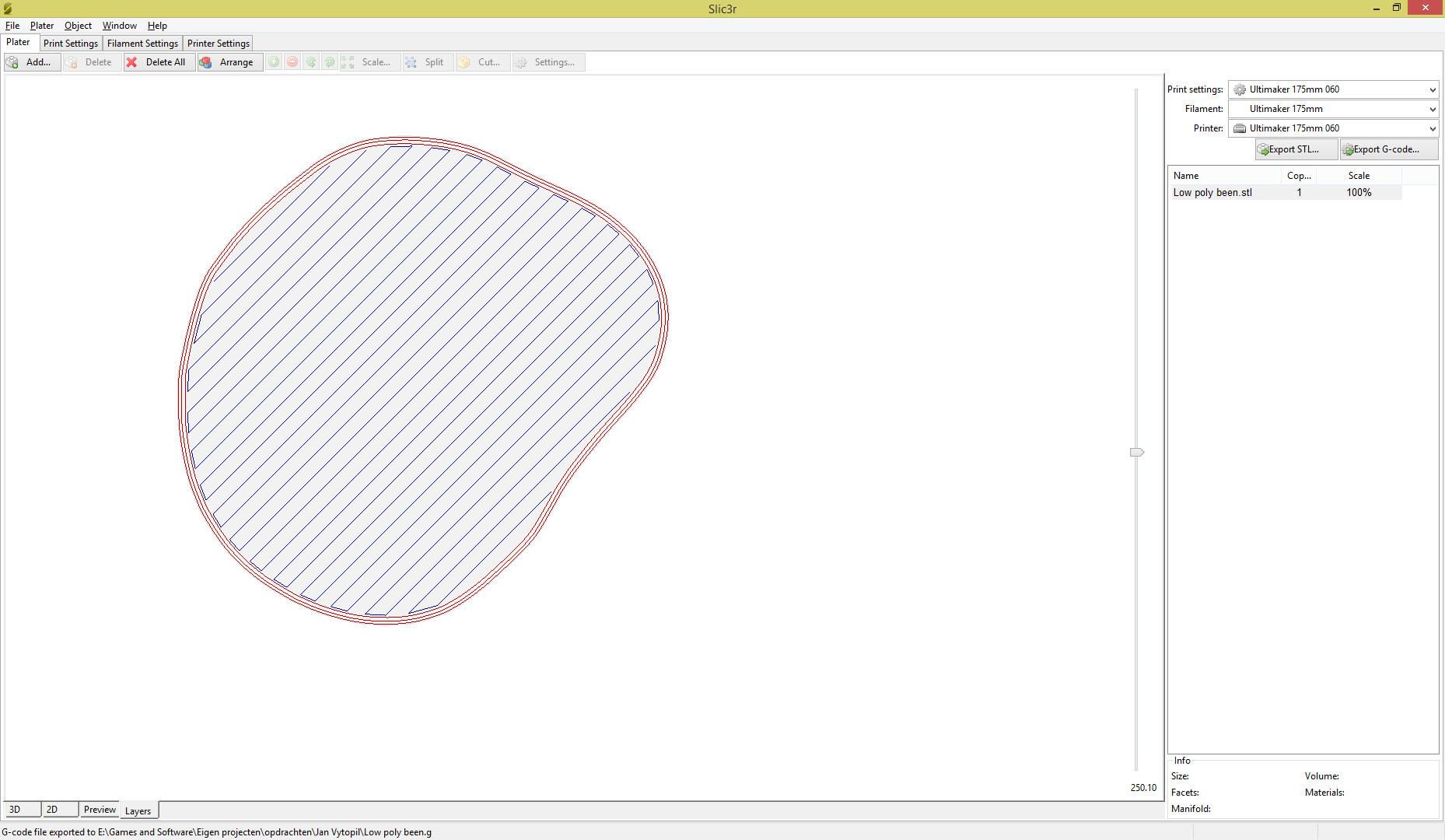
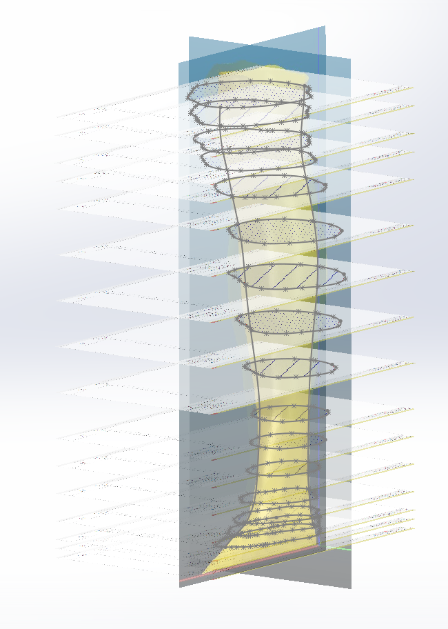
Now for the shape of the fairing itself. I had a 3D scan of the opposite leg. Solidworks however is parametric design software. It does not accept any form of polygonal file. The file had to be converted to something that Solidworks could understand. For this I used a workaround. Solidworks has a spline function, and a loft function. These can be used to make shapes too exotic for normal functions. To use the spline, the intersection of the scan of the leg on several places is needed. For this I used Slic3r.
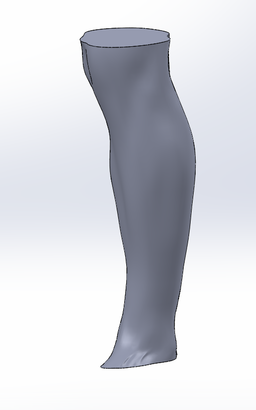
I modified the scan so it was treated as a 3D printable model in Maya. Scans are not manifold. They generally have a big hole where the scan ended. In my case this meant that the top of the leg and the foot were open. Simple boolean functions were used to make a solid shape with a flat top and bottom out of the scan. Then I imported the design in Slic3r and got the intersections at known location of the scan. These were then inserted in Solidworks on all the right locations and scales and traced with the spline function. Several guide lines were also drawn based on the outline of the scan. The loft generated a nice looking model of the leg. Having the shell of the fairing and the prosthetic in Solidworks, the process could start.
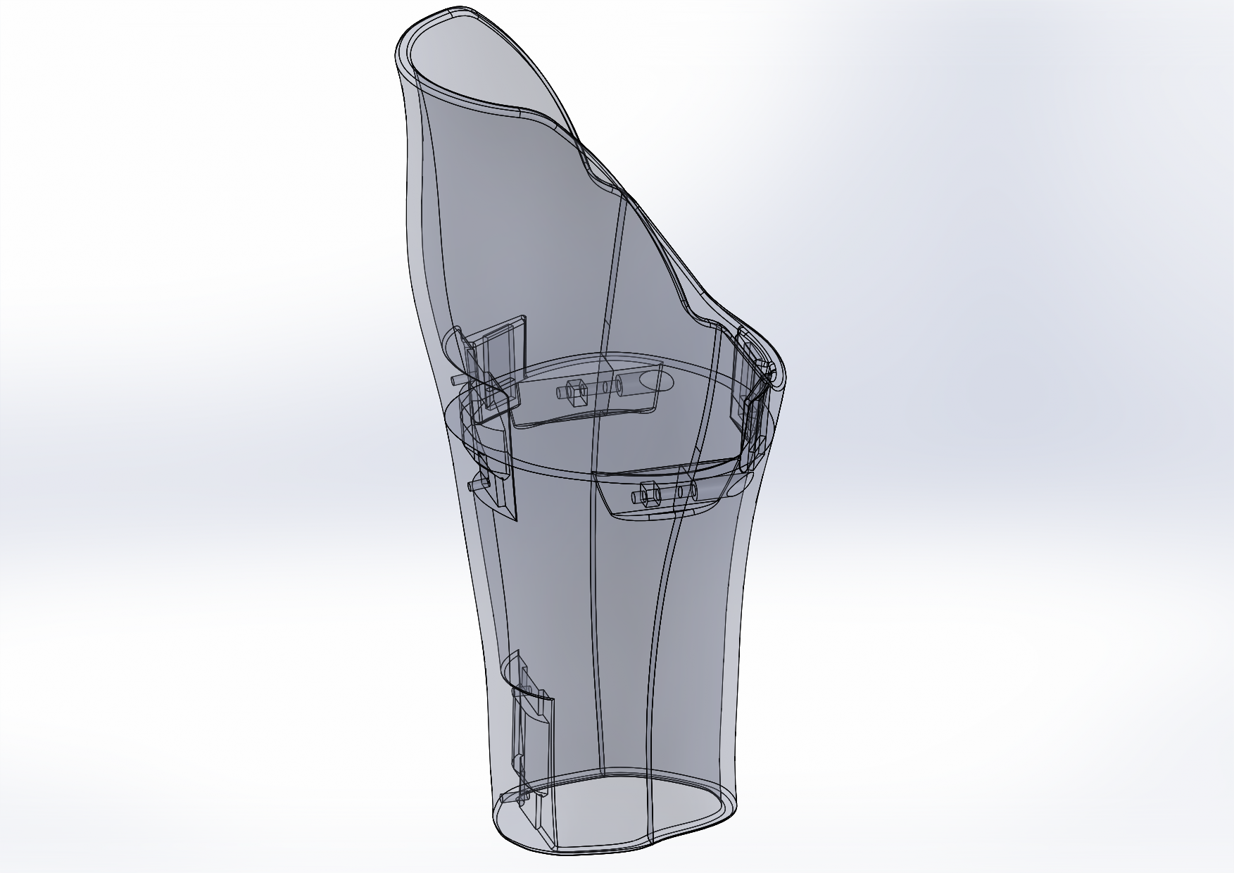
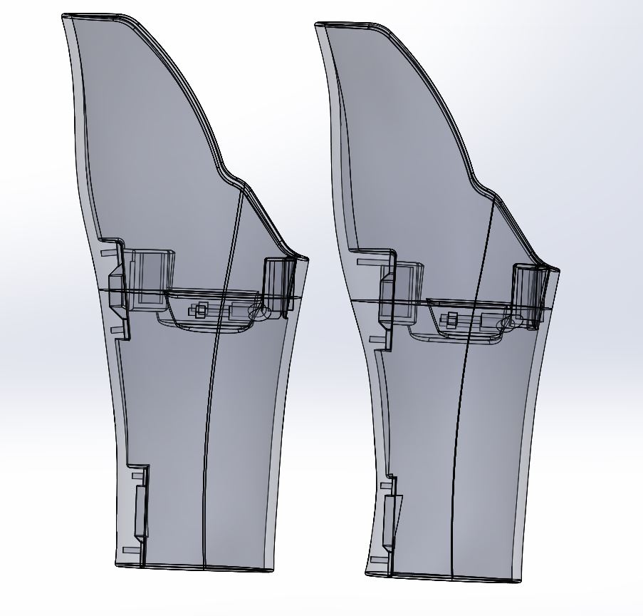
The first step is to generate the rough shape and convert it into a shell. The idea it to create a shell that will cover as much of the prosthetic while keeping all the freedom of motion. The only moving part is the knee, and it moves only backward, around 120-130 degrees. The foot is static around the ankle. The foot itself is slightly flexible, but the ankle is stiff. This means that no extra precaution are needed around the ankle. With this in mind, the shape as seen in the images makes the most sense. It has fairing in most places, and a big opening at the back of the knee to allow a full range of knee movement.
The second step is to split the model in 2 halves. The split happens on the widest point of the leg so there is as much space as possible for the mounting mechanisms.
The third step is to add the mounting components. This can vary from prosthetic to prosthetic, but the basic design is based on straps to mount the front shell to the prosthetic, and screws to mount the back halve of the fairing to the front halve. There are small notches in the part. These are for strips of aluminium to align the shells when gluing.
The final step is to split the model for 3D printing. This can be done in several ways in Solidworks, and I’ve done it several ways throughout the development. The way I show in the images below is by creating a physical model of each of the split parts, all with the same base. Later I simply kept all the splits in the same file and saved them to different files as the last step. In retrospect this was way better, but you learn along the way.
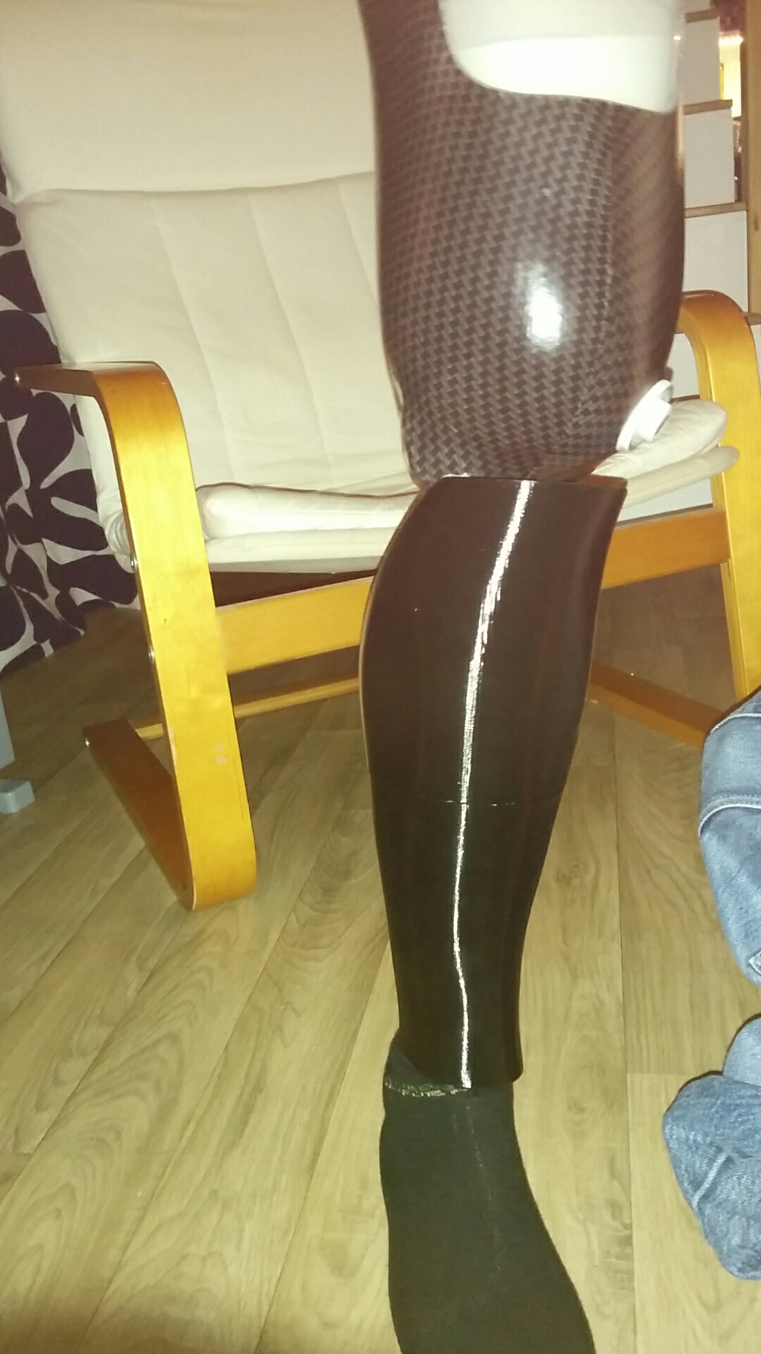
The first itteration was 3D printed in PLA. This whole process took 12 hours of print time and 350 grams of PLA. The whole shell was temporarily taped together for fitting. A first observation was that PLA felt flimsy and brittle. 2 long protrusion on the back halve of the fairing felt like they would snap at the slightest contact, and the whole fairing creaked when you squeezed it. Upon fitting it the hole reserved for the prosthetic barely wide enough. The back end left too little space for the knee to bend fully (remember that his knee bends further than most peoples). More importantly there was a new prosthetic to fit around, which was a lot wider than the old one. This would have been frustrating if it weren’t for one last tiny problem. I had never mirrored the original scan. I had created a beautiful recreation of the remaining leg.
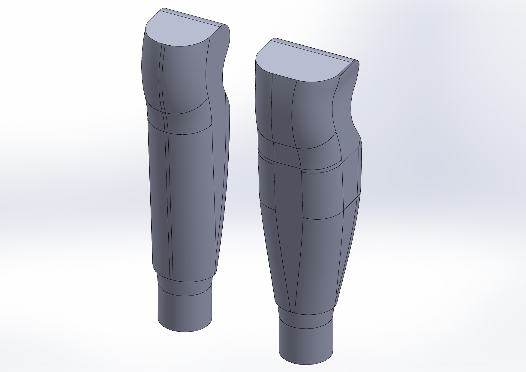
Back to the drawing board. First of, the new prosthetic was drawn into Solidworks using new reference images. There were several improvements made to the fairing. First of, each fairing half would be split in 2 parts, not 3, reducing the amount of glue joints. The back end of the fairing was opened more and the long, fragile protrusion were shortened. More space inside the fairing was made to accommodate the new prosthetic. Also, the 2 brackets for Velcro were reinforced with a strip of aluminium. Also the design of the fairing was actually mirrored. I was not going to make this mistake twice (right?).
The new design was printed in Colorfabb Ngen. A PET like plastic that is a nice print and leaves a strong part. The fairing feels a lot stronger than the previous one. Print times and material are roughly the same as the previous fairing.
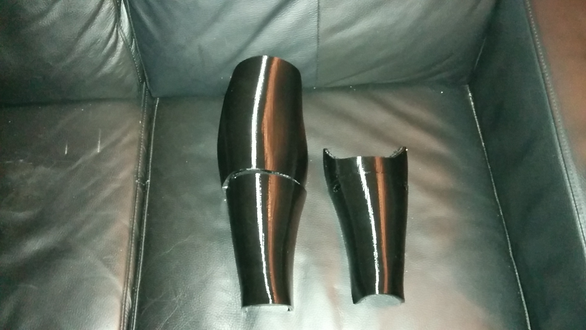
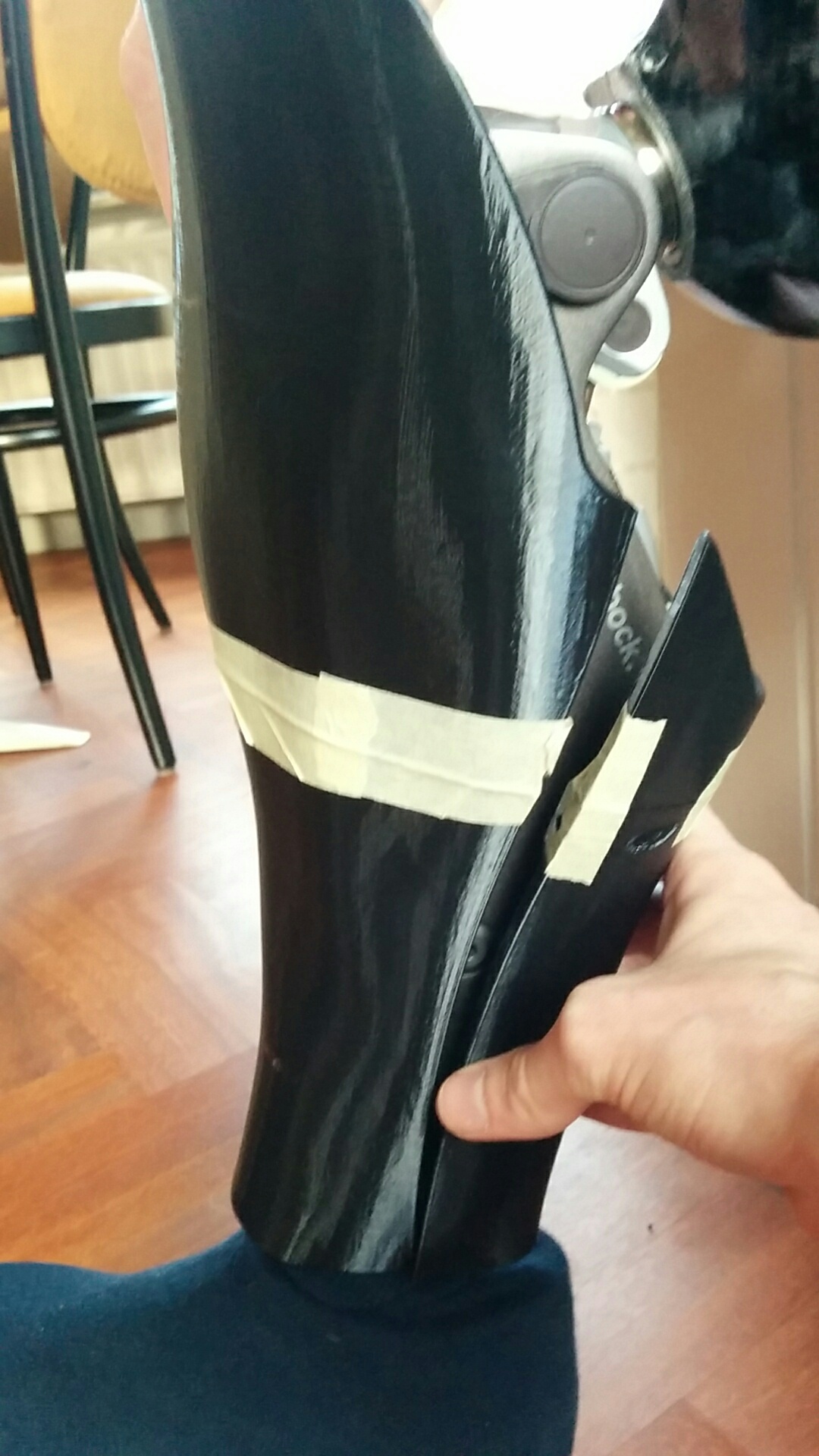
The next fit. It was actually the right leg (a good start) and the front fit fairly well. Only the back would not fit. A small gap of 1-2cm would remain between the 2 fairing shells. The gap for the prosthetic was too small. Also the front of the fairing tilted too far forward, breaking the line with the leg.
Back to the drawing board (again). First, with better measurements and better photos, the prosthetic was measured (again). Due to perspective, the 3D CAD of the prosthetic was a few centimeters too narrow. This time the model was corrected with actual measurements and give some extra bulk, just for safety. The outside of the fairing was altered slightly to make more room for the prosthetic. Also the internal mechanisms were tilted to allow a better fit to the fairing, and give more room. The fairing was printed (again) in Ngen.
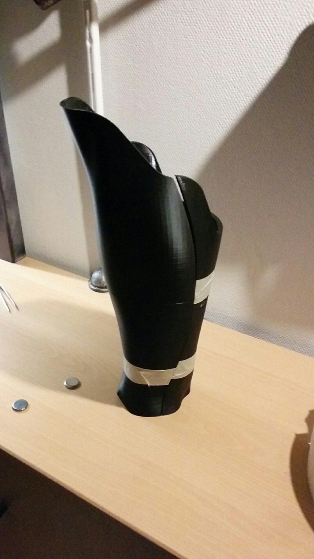
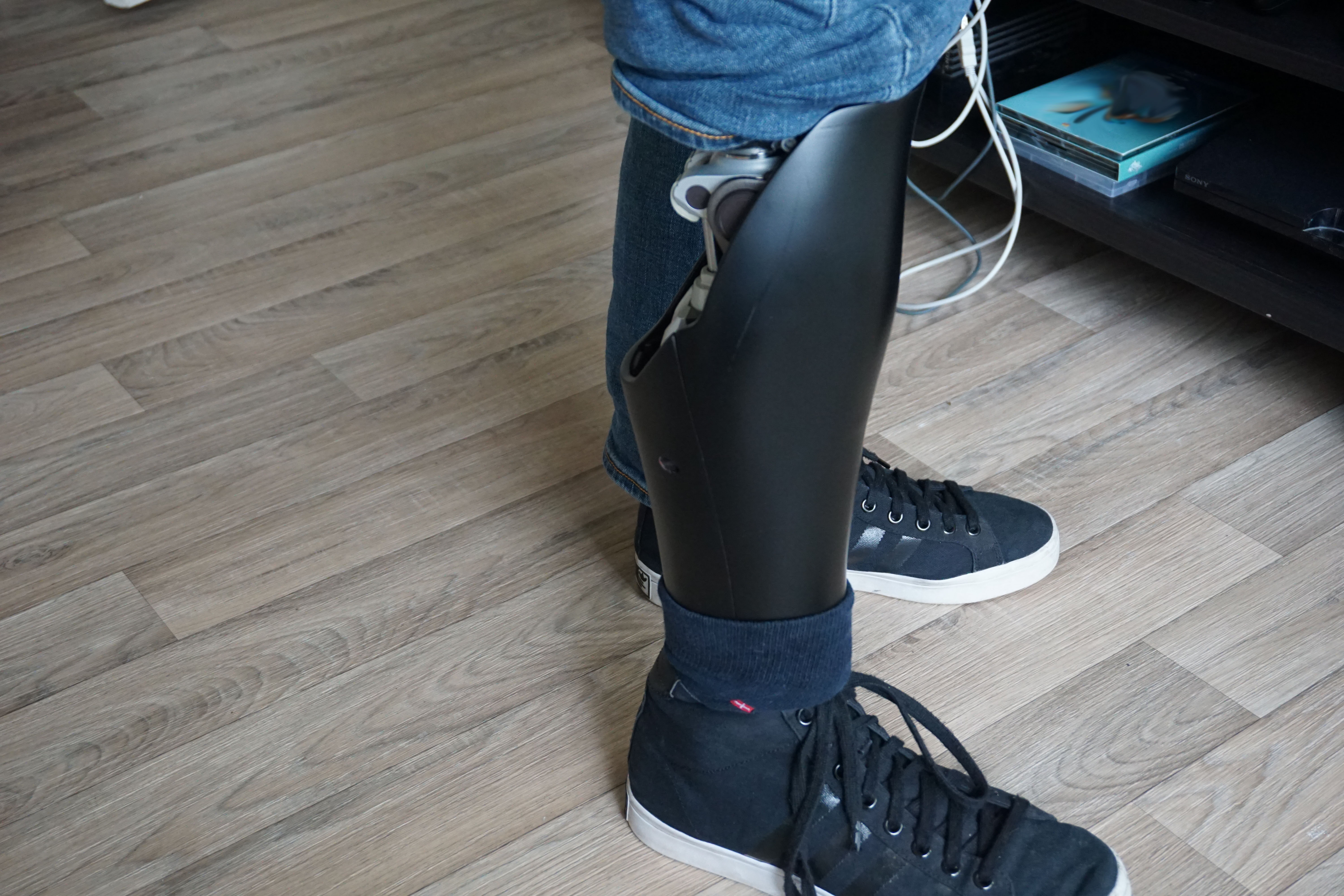
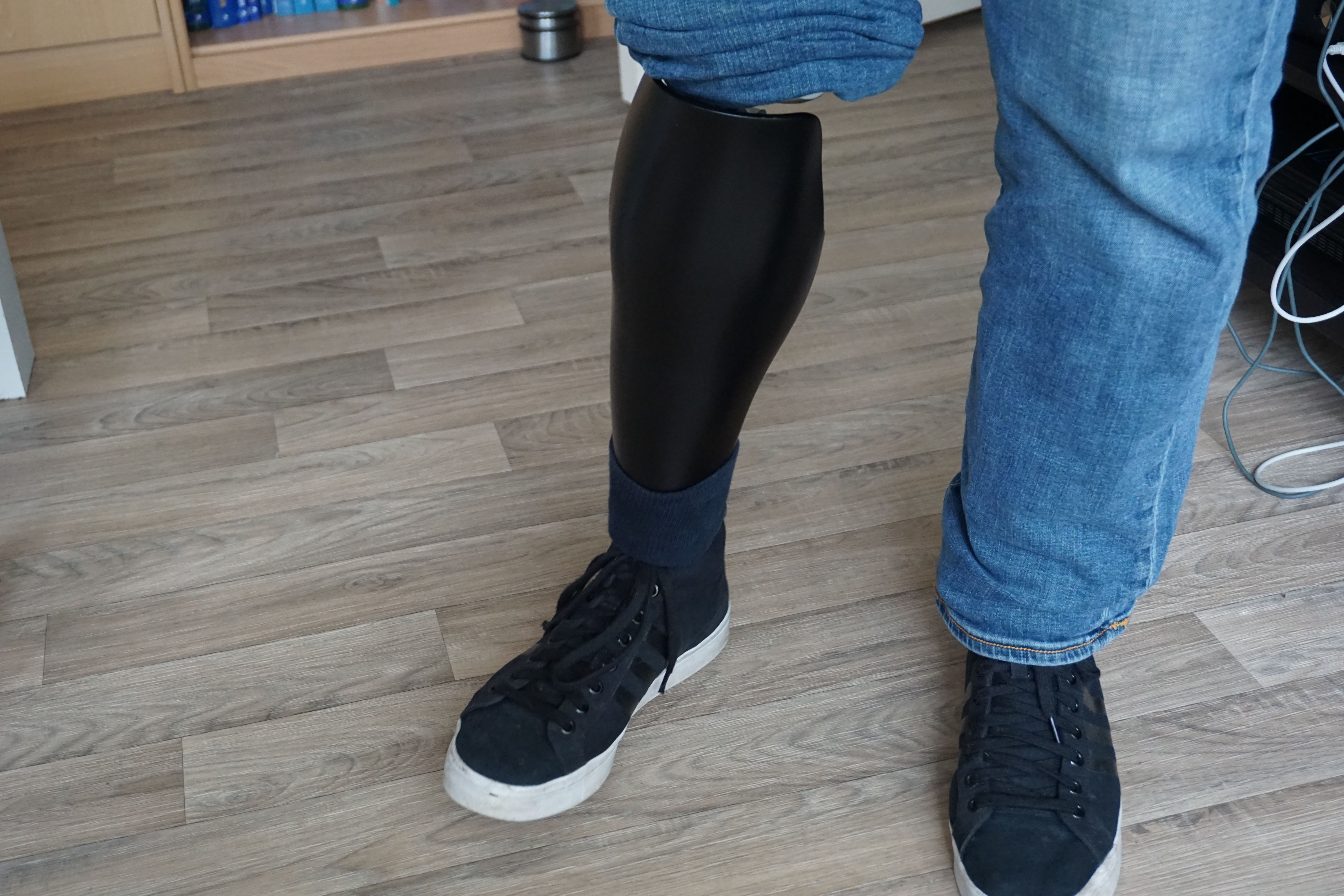
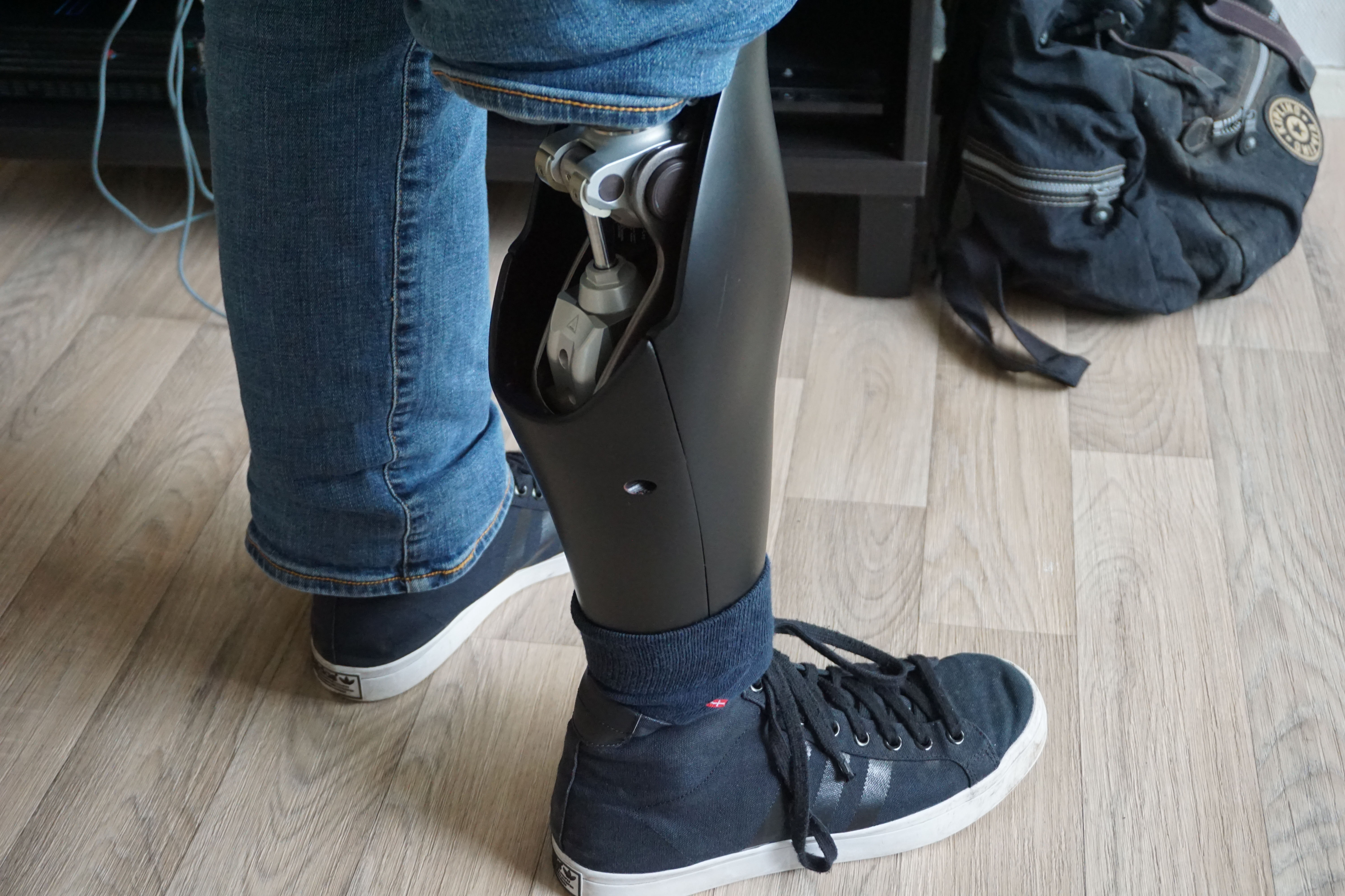
After printing was a third session of fitting. This time the fairing actually fit. No real problems. The fairing has at a little bit of play left. At this time I will admit that I still had less left than I had intended with the prosthetic redesign, but it was enough. The only thing (as visible on the image) is that the fairing is slightly hanging to the side, but this can be fixed with foam to force the fairing in a direction. Finally, the fairing could be finished. The fairing was going to be a plain black, with no hint that this fairing was actually 3D printed on the outside.
The first finishing step was to completely sand the fairing. Only the outside and the inside of the top halve will be finished. The rest of the inside will not be visible anyway, and would be really difficult to finish. Ngen sands relatively well by hand, but sanding any 3D printed plastic with a machine is not advised. The plastic tends to melt when sanded too roughly. The fairing was sanded with incrementally fine grains of sandpaper, starting with 60 and ending with 180. After this sanding most evidence of 3D printing was already gone. After sanding the fairing was coated in XTC3D epoxy. This is a special finishing epoxy that both reinforces and smooths out the part. Since the fairing was already sanded, only one coat was used. When the epoxy had set and had a few days to cure, the fairing was sanded again. This time all the sanding was wet, and started at 200, working up to 600. The wet sanding already left a good finish, but to fully smooth the part, 2 more layers of filler primer were applied. Each coat of filler primer was sanded down with 600 grit wet sandpaper stopping when the epoxy layer gets close.
Painting was done with automotive 1K matte black paint. I tried to not use the cheapest of the cheap paints here, trying to get a tough surface. Several coats of paint were used. After the first coat I had to use wet sanding to get rid of a runner in the paint. After that I stopped sanding. The paint job was finished with several coats of satin finish clear coat. Be aware that the clear coat can remain fairly soft for a few days.
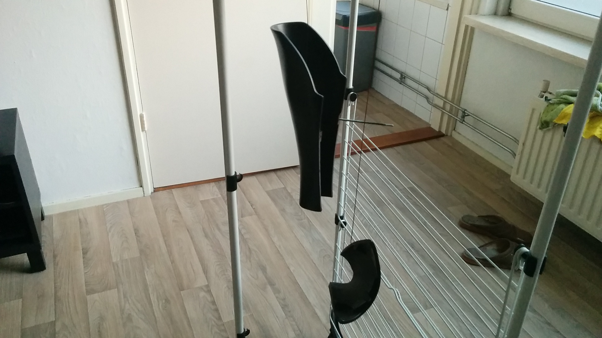
Some final finishing things were done. The nuts in the front shell were glued in place using super glue with activator. The inside of the fairing was lined with strips of cell rubber to lock the fairing against the prosthetic. After the final points, the fairing was fitted to the prosthetic. And with that, the fairing was done. There are already a few tiny scratches on there, but all in all, it looks great. The matte black looks really neat, and the fairing fits quite well. I especially like how the prosthetic looks in combination with the fairing. It does not distract from the prosthetic, it adds to it. The mechanism that holds the fairing in place is not the most refined mechanism possible, but it is simple and it works. Two important properties of any mechanism.
For now, I am done with fairings. I have learned so incredibly much from this process, both what to do and what not. I do want to give it another go in the future if it can help someone, but it was a very tiring process that took way longer than anticipated. If there is anyone from the Netherlands (preferably region Twente) that reads this, with a prosthetic that wants a fairing, do use the contact form to get in touch. I will not promise I say yes, but you can always try. Form any other country, I think it would be better if you found someone else to make one for you. Maybe someone who read this article and was inspired.
I am really happy with the result, and I have been told that the fairing is still holding up well. There are however things I would have done differently if I would do this again. Here is a list of my future improvements and things to keep in mind.
- When you get a 3D scan of the leg for reference, also get a 3D scan of the prosthetic, with socket. This goes 2 ways. First, it gives a good reference for the prosthetic. Second, it helps with the alignment of the fairing. While the alignments went fairly well I have had to do 2 (TWO!) redesigns of the fairing to compensate for a wrong model of the prosthetic. Admitted that the first time the fairing was also mirrored, but even then it would not have fit.
- Also mentioned in the point above. MIRROR, THE, REFERENCE! Else you will only make a pretty replica of the still there limb, not a fairing. Get on a piece of paper, the side of the body you are making the fairing for and look at this piece of paper every time you work on the fairing.
- When printing in more than 1 part, add alignment notches. You will thank yourself when gluing the fairing together. I had some notches in place, but hardly enough.
- If in any way possible, try to print a fairing on a plastic SLS printer. The fairing will be infinitely stronger than on an FDM printer. If this is not an option, avoid weaker plastics like PLA and try to get stronger plastics like PET. I personally dislike the use of ABS for anything, but if you are an ABS person, use that. This thing is on a limb, It will get hit somewhere in it’s life.
- Get something more durable than automotive paint. While the finish looks absolutely amazing, just in handling I have added a few scratches. I can’t help but think that a more durable coating exists to cover a fairing. Some sort of epoxy coating? Another idea is to print the fairing in a finished state. Print it so pretty it is done immediately. Obviously this means printing it in one go, requiring a big printer and more print time, but it might save weeks of finishing.
- Keep secondary functions in mind. prosthetics have a microcontroller on board, and require charging every few days through a charging port. If there is no hole in the fairing, either it needs to be really easy to take off or it will need an additional hole. I have been told that the fairing now has an additional hole for the charging port, that was not originally in the design.
- Maybe redesign the mounting mechanism. It now takes 2 screws at the top to mount. There is nothing at the bottom holding it together and it is hard to put on by yourself. Maybe a better design is possible that has something like a hinge, or a latch. Also some alignment notches between the front and back shell would have been helpful for keeping the fairing look nice.
- For fitting the fairing to a prosthetic, use something else than cell rubber. I have considered for a while to use expanding foam in a plastic bag. Mount the fairing on the prosthetic and place a bag with expanding foam between the fairing and the prosthetic. This way it should be possible to make a foam insert that exactly takes the shape of the prosthetic. Alternatively, you can also use the 3D scan of the prosthetic to make the fairing fit perfectly, though some sort of liner would still be desirable.
- If you do have the skill set, use something different than Solidworks. On the one hand it makes the mechanisms fairly easy to design. On the other hand the organic looking shell is a tough one. Personally I would still go for Solidworks, but it is my job to use it. If you are better at something more polygonal, use that.
(PS. I only got it mirrored once, luckily I am not stupid enough to make that mistake twice)
(PPS I do apologize for the lack of photo’s along the way. This project was never really made for publishing, so a only few photo’s were made)





Hi it’s so cool thx a lot for your work my sister is below knee amputee I want to help her feel better about her prosthetic
Awesome work !!, a friend of mine lost his lower leg due to a motorcycle accident and would like to try your design / model .
If you could please send the model or a link to the model.
Thank you
Hello,
Contact me through the contact form and I will share the files with your.
Hi, could i please get this stl. I have an elderly guy next door and id like to print it for him.
Send a message to me using the “contact me” (under info) so I have an email address I can send it to.
Hello my dear friend! Could you send the fairing file? I tried to do something myself, it turns out to be complete nonsense (. I would try your project. Regards Eduard
Do you think this could be adapted to work for a below knee prosthetic? I have a 3d printer and I really want to make a cover for my leg.
There should be no reason why it could not work. As long as you have something to mount the fairing to, you can make this work. It would require you to make this design however.
Hey, I’m 23 yrs old amputee that happens to use same leg as you designed cover for. I would really appreciate if you would send me your data so i could make it “fit” my leg. Especially I’m after cleg4 as that’s what I’m using now, planning on getting rx80 (blue one that you also showed) but that’s not that important for now.
Thank you for taking your time, greetings from Poland 🙂
Contact me through the contact form. I can send you the STL files if you promise you will not post them elsewhere. I cannot send source files because this is based on a 3D scan of an individual.
Hey, i tried before writing that comment, and also tried just now. For some reasons it’s saying there was a problem and to contact administrator
serait-il possible d’obtenir une copie du fichier STL pour imprimer car j ‘ai la meme prothese suite a une amputation l’année derniere
serait-il possible d’obtenir une copie du fichier STL pour imprimer car j ‘ai la meme prothese suite a une amutation l’année derniere
My friend sent me here to check this out to see if this was something I can print for her prosthetic. Fantastic work! I’m just getting started with 3D printing, would it be possible to get a copy of the STL file to print and learn from?
I sent the file by mail. I hope it helps you.
Hello, I am a prosthetic orthosis expert in Iran and I have been working on orthoses and 3D prostheses for some time. I wanted you to cooperate with me if you want and send me the file of this leg so that I can test on my patients. I hope it helps them. I designed a leg that I can send you if you want.
Please contact me through the contact form so I have your email address I can send you the files through. I made this project as a one-off, so I cannot guarantee that it will be of any help, but I can always send it and let you see if it works or not.
Mijn vrouw heeft een zelfde soort prothese en nu heb ik hetzelfde idee opgevat. Nu vroeg ik me af, heb jij de tekening van de c-leg nog en zou je deze met me willen delen? Het zou al veel schelen als ik alleen het been zelf hoef te tekenen.
Ik heb nog een mockup tekening van de Cleg. Ik kan niet 100% garanderen dat deze perfect is, maar hij zit wel redelijk in de buurt. Ik heb je Email adres al, geef maar aan of ik deze mag gebruiken en welk formaat je wilt hebben. Anders kun je mij prive bereiken via het contact formulier om verdere details te bespreken: https://ytec3d.com/contact-me/
That looks awesome.
Where can these be bought?