Heat exchangers are devices that transfer heat from one flow to another. This flow can be any liquid or gas, but all exchangers described on this page exchange air to air. If there is heat involved, a heat exchanger might benefit the process. For domestic use heat exchangers are a great addition to any ventilation system in a cold environment. By adding an exchanger between the outgoing and incoming flow, the temperature can be exchanged between them. In the case of a 100% efficient heat exchanger, all of the heat will be exchanged. The dry, fresh air from the outside can be replaced with the humid, stale air from the inside while keeping the heat inside.
Heat exchangers work by passing 2 flows of air past each other separated by a (thin) wall. The heat naturally moves from the hotter side to the cooler side, through the wall. The only energy required is to get the air moving. There are several ways to make the flows of air pass each other. The flows can cross, perpendicular to each other, run parallel to each other. In all examples on the page the flows of air run opposite to each other. This setup gives the highest potential efficiency (nearing 100%).
My own house has ventilation issues. While I can just open a window in the Summer, in the winter I would waste a lot of heat that way. I always wanted to make a heat exchanger, so I used this opportunity to make one.
More information on logging and efficiencies can be found on the Instructables page: https://www.instructables.com/id/Heat-Exchangers-and-3D-Printing/
Data logger
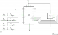
Making something like a heat exchanger without testing it is rather pointless. Because of this I also made a data logger to measure all temperatures and get a ball park figure of how efficient all exchangers run. The logger consists of an Arduino Uno with 4 10k NTC’s. The Arduino measures the temperature of every NTC at set intervals and logs these temperatures on an SD card. This data can then be pulled from the card and imported into something like Excel to get fancy graphs.
Partially 3D printed version 1
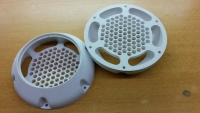
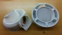
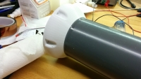
The partially 3D printed version uses 3D printing to make the complicated parts. The parts that do the exchanging are fairly simple to come by. A 90mm PVC tube is used as a body, and long drinking straws are used to exchange the heat. Straws are used because they are cheap, have lots of surface area and are fairly easy to come by. The end caps cap of the tube. The straws are fed through the end caps, making lots of tiny channels through the tube. End caps separate the flow through the straws and the flow around it. One of the flows of air moves through the straws, while the other moves around the straws.
The exchanger with end caps is around 1m long, 24cm wide and 14cm deep. It is made from PVC, PLA and probably PE. The straws are 75cm long, have a diameter of 6.5mm and a wall thickness of 0.1mm. There are a total of 91 straws in this exchanger. Accounting for some losses in manufacturing, the total exchanging surface area of the exchanger is 12500cm². Over a square meter. Measure efficiency ranges from 65% to 75%.
If you downloaded the files from this site and liked it, please consider going to the Donations page. This will help the development of more free designs and plans.
Fully 3D printed version 1
The fully 3D printed heat exchanger is (as the name suggests), completely 3D printed. It is printed on an Ultimaker with an E3D V6 with 0.25mm nozzle. The material is PLA, the wall thickness is 0.3mm and the layer thickness is 0.16mm. The dimensions of exchanger without caps is 15x8x7cm and the internal surface area is 1000cm². The total exchanger takes around 10 hours to print. While the walls are thicker than on the partially printed exchanger, the fully printed version requires little assembly. The thicker walls make the exchange rate a bit slower, but it still performs quite good with an efficiency of 50% to 65%.
 If you downloaded the files from this site and liked it, please consider going to the Donations page. This will help the development of more free designs and plans.
Real test
The original test was to properly ventilate my home without wasting all the heat. On the ventilation grille above the window 2 adapter were glued. Vacuum cleaner hose was attached to these adapters. The rest of the grill was taped of to prevent unwanted flow in and out of the house. Fresh cool air is drawn from the right adapter, and the exchanged stale air is exhausted to the left adapter. The exchanger sits in between, with the logger logging the temperatures.
The air quality of the room has improved quite a lot from this setup. Without the fans running the air feels used up. After 8 hours of running, the air is just fresh, without anything special to note about it. There are some issues in the implementation. The hoses prevent the curtains from being closed and fans are quite noisy. Without filters I am wondering how long it will last before clogging up, but time will tell.
Conclusion
The heat exchangers tested so far work better than expected. All of them preformed above 50%, and in some cases above 75% efficiencies were measured. The most surprising thing was not how good the partially 3D printed version worked, but how well the fully 3D printed version worked. For something with those thick walls, the efficiency was rather surprising.
I think that I need to know more. I want to to a bigger followup experiment, with more variables measured (pressure, flow, humidity, temperature) and more different, smaller designs. I want to see the effect of different materials, different flow paths, wall thicknesses, length and surface area. I also want to plot graphs on flow vs. efficiency and temperature difference vs. efficiency. For this I will design a better logger in the future, that will plot these graphs for me and preform all of the testing automatically.
There is a lot more to learn about these things and I want to know it.
License
The project described on this page is licensed under the Creative commons – Attribution – ShareAlike license.


I’m trying to make something similar to this. It’s my first foray into larger 3D prints so I’m not sure how it’s going to go, but I’m keen to know what you think and if you have any suggestions / tips.
The plan is to have this sit in my bathroom window, running 24/7. The window opens vertically so it’ll sit at the base of the window and the window will close onto it, forming a seal. It’s powered by 5V (USB) running two 40mm CPU fans on either end. The middle consists of a snake of 4.7mm checkerboard counterflow of cells produced by adjusting the infill settings of my 3D printer software and disabling top and bottom layers. I’ve printed it in ABS to handle sunlight and been gluing the pieces together using acetone. At each end of the unit I switch from cells to slices, do a U-turn and then switch back with the idea that I may add something to swap airflow periodically to flush out any condensation that has built up on the intake side.
My designs are here: https://cad.onshape.com/documents/258973d434188b8846a4521d/w/1c55cf682c477f1301c4753b/e/4564c6d3e991e0decacc67e1?renderMode=2&uiState=63df320fc5318659cf180f03
I have some concerns that I won’t get enough airflow (I expect 5-8 hours to cycle the room based on CPU fan stats) but at the same time, I believe that slower airflow is key to higher efficiency here as the thermal conductivity is measured in W/m·K so the slower the air goes through the device, the greater the energy transfer.
WDYT?
I have not worked on it for a while, and I was never the subject matter expert, so do not see my opinion as an expert assessment.
I can not open the files since I need an account to see them.
The only thing I can think of is that the 40mm fan may not be capable of actually moving a real amount of air. PC fans are built for flow, and less for pressure. Heat exchangers have a pressure drop, which strongly reduces airflow. I would still try it, but have a plan in place to change the fans if needed. Slower airflow might increase the amount of heat that can move from the air to the exchanger, but it also gives the heat more time to travel through the heat exchanger. Most heat exchangers only contact the air for a few tenths of a second anyway. It is something you can tinker with, any heat exchanger has an optimal amount of airflow. Much lower or higher will decrease performance.
Hi, this is great work. Would you have time for a quick call? I would like to invite you as an expert to talk in a business meeting about 3D Printing of heat exchangers in the next week. How can I contact you? You can also text me or call me. I would highly appreciate hearing from you 🙂 Best, Caro
caro@2bahead-ventures.com 0049 171 835 4030
The contact form works fine
Hi,
thank you for your work!
I have an answer, in the version total 3d print, the fan (air in and air out) can work
simultaneously or can work only fan out and than fan in?
Very good job!, Plastics are the key for air an fluids, I have been in the HVACR industry for over 48 years and seen many types of ex changers. The ERV’s and HRV’s are very cool, about 18 years ago I had my students build a ERV with a core that was 12″ x 12″. We recorded very nice results in the 57% range, we then went back and build another core with the same material, however we fused it with a solvent. The core produced 76%. Problem with metal, being either aluminum or copper is corrosion. This has always been an issue with air or fluids, this causes periodic maintenance. Plastics is the key! The thinner the better for the heat exchange with air and lower static pressure. Fluids we have pressure issues in the commercial industry, with pressures around 25 psi, thin plastics that can work with that pressure is the direct needed. Drop me a note some time.
This is absolutely amazing – im awe-struck !!
thanks so much for keeping this open source too, i cannot walk and pretty much live in a tiny box room so in winter it gets harder to open a window but because i love soldering, i try to leave the window open and have a 120mm flexible ducting attached to a fan so it sucks the soldering smoke out my room directly, but heres the major problem..
as i could potentially be soldering for 4-7 hours at a time, im usually wrapped up, in BED, looking like an Eskimo lol, woolly hat, 2 x t-shirts, jumper and a darn coat lol i draw the line at gloves as i need a good grip on the soldering iron, as if its not dangerous enough soldering whilst in bed lol
so this will help so very much keep as much of the heat as possible and just break down my soldering sessions to 1-2 hours a time so less smoke fills the room in these stupidly cold times of year, i love that straws-design, found straws on ebay for about £15 for a pack of 100, bit expensive but if it improves my air quality in my room then its a worthy save.
As being in bed 23 hrs a day means its harder to keep body heat too, so a huge thank you again.
I see you don’t monetize your site, don’t waste your traffic, you can earn additional cash every month because you’ve
got high quality content. If you want to know how to make extra bucks, search for:
Boorfe’s tips best adsense alternative
Hi,
congratulations, this is a very useful web side. I printed the “fully 3D printed version” just to get an idea, how the internal air is flowing. But after printing the STEP-file, it is just an open tube with no internal channels for the heat exchange air flow. Is this intentionally or is this part missing in the STEP-file?
Yours Johannes
I suspect you mean the STL file. The ribs on the inside are really thin and require a 0.25mm nozzle (maybe 0.3mm) to print. Some slicers will just drop details like that if the nozzle is any bigger.
Dragonator,
Thank you. I had long time ago the idea of a straw-based unit. You just helped me make it real.
I constructed a supersized version, 151 straws 92 cm length, in 125 mm PVC pipe, with 120 mm PWM fans top flow 155 m3/h. And it works, shockingly well ! full story and lots of pictures in the comments added here: https://www.instructables.com/id/Heat-Exchangers-and-3D-Printing/
Design public free on Tinkercad.
Kind regards,
Vlad Christian
I had a chance to look at your design and I think it can be further improved if you use shell-tube design with baffles (these are complex to construct for mass production, but hey you are using 3D printing.
My suggestion is also to make the tubes with hexagon shape and arrange them as https://encrypted-tbn0.gstatic.com/images?q=tbn:ANd9GcSgLBG4VJ2tLsUTfp-wuPT7HSt9MGDPj2tM7-PIbq1rvIOW7xz-, but rotate the image by 90 degrees so the flow to be from left to right, then baffle will force it from right to left and so on. Additionally you can try the tubes to change hexagon size slightly in zik-zak manner so it can force turbulent flow inside the tube (which should improve more air to get in contact with the walls).
This design will increase the air resistance, but you should get better efficiency.
Best of luck!
Hi,
Did you do any experiments with the 90 degree grid pattern like in the old Hitachi systems? Why did you go for this design? I’m thinking of making something like this for my camper van, and your design is very neat looking..
The designs here are mostly experimental and proof of concept. The counter flow is said to be the most efficient, with 95% efficiency possible. I don’t know if the designs are already mature enough to be put to use, but you can always try. The 90 degree grid to my knowledge is easiest to make and has the lowest resistance, but efficiency peaks at 70%.
I do want to make the proper tools to measure these exchangers and do a lot more tests this winter.
I absolutely love this. I live in southern california, and our problem is the opposite, we want to keep our incoming air cool. I wonder, what kind of efficiencies you would get on the fully printed heat exchanger with copper or silver filled pla?
This is actually a discussion filled topic that I hope to learn more about next winter.
It is actually not completely clear whether metals such as copper improve the efficiency by that much (or at all). The gut feeling says it should, after all, better heat conduction means better efficiency, but plastics seem to work in heat exchangers way more than they should. The idea is that getting the heat from the air to the wall material is disproportionally more difficult than getting it through the wall itself. The next winter I hope to do a lot of experiments with a better test setup to determine the effects of heat transfer of the material, surface area, turbulence, thickness and general design. This will also include a showdown between copper, aluminium and plastic.