Home › Forums › 3DP printing › Step 1, Hacking the CN642A inkjet printhead
- This topic has 75 replies, 6 voices, and was last updated 9 years, 3 months ago by
yegorvd.
-
AuthorPosts
-
November 1, 2014 at 7:27 pm #1975
dragonator
KeymasterWelcome back old friend, long time no see.
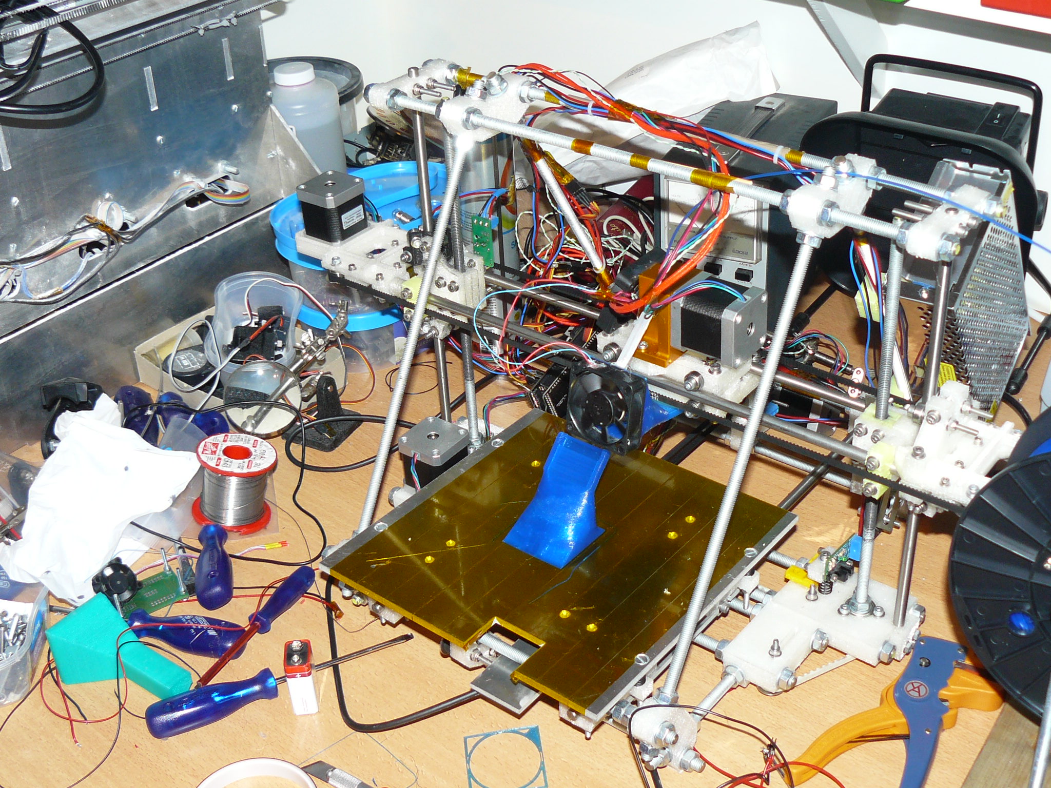
My mendel is finally running again. This took weeks longer than expected (hence the me not responding), first because the extruder I had did not work at all, then cooling problems, then a non functional slicer and then missing steps (which are still present). It now prints on an acceptable level. Tomorrow I hope to 3D print and test the CN642A cartridge carrier.
And other, important-er news. Last Thursday I had a meeting with the people of Ultimaker. For anyone that doesn’t know, Ultimaker is a Dutch, open source 3D printer builder. They were one of the first n the market and also are responsible for some of the most important things in open source 3D printing, such as marlin (firmware). They are also experimenting with inkjet printing and are also busy with the CN642A. They also have a CN642A carrying printer and have figured out the logic level (the 1,5V) themselves too. They are now waiting on more parts to test with this level and in the next few weeks they will see if the information to the printhead is somehow encrypted. If it is, they will probably drop the 642, if it isn’t, they will also develop stuff for the 642. Why do I tell this… They are willing to share their knowledge and let us help each other. They might enter the forum in a few weeks.
Also we might be able to use their next electronics in then next 642 version of plan B (project Iris). If this is possible it is a great step forward, because then we have an open source, marlin compatible developed 3D printing board that runs much, MUCH faster than the current Atmega2560 driven boards. Something that is necessary for fast 3DP printing. That is just a hope for now, but I thought I’d share it.
Anyway, I will keep all of you posted on any progress, both from me and if I get it from Ultimaker, and until then, enjoy a picture of my newly fixed Mendel.
– Yvo out
 November 1, 2014 at 9:42 pm #1976
wonko
ParticipantThat sound fantastic! I have followed the Ultimaker project from the beginning and I have seen the printer at some Dutch trade show. I would be happy to share whatever I find out about the head as well.
I did manage to wire up the 24-pin connector in the print head board, and I found various voltage levels from 1.5 to 5V. I should be able to hook up the logic analyzer safely next week.
Most exciting stuff!
November 2, 2014 at 4:30 am #1978sealdogfish
ParticipantHas anyone seen this:
It can’t get much simpler than this once you have the DAC set up right.
90 Black, 30 x 3 color nozzles.November 2, 2014 at 2:32 pm #1979ezrec
ParticipantHey! I have a Phase 840 wax printer! I can do this!
November 4, 2014 at 7:57 pm #1982ParticipantOK, I had a chance to connect the scope. Careful though: my printer generates no color – one of the 32V lines may be bust. Measure before you connect a logic analyser yourself. Don;t rely on my measurements.
Pin / All black text
 1, 2   0V (GND?)
 3      0V while idle, const 5V while printing (head electronics power?)
 4      0V, const 1.5V while printing (1.5V reference?)
 5      0V, 1.5V few long pulses
 6      0V, 3.5V, pulses 1us long
 7, 8   0V, 30s sine wave around 1.5V (+-0.5V)
 9, 10  0V, 1.5V with sine wave disturbances at 60us
11      0V, 3V, slow pulses
12      0V, 3V, pulses around 10us
13      0V, 3V, pulses around 100s
14      0V, 3V, clocks at 3us
15      0V, 3V, pulses between 10ns and 1us
16, 17  0V, 1.5V +-0.5V pulsed, sine wave (noise?)
18, 19, 20, 22    0V (GND?)
21, 23, 24        2V, 32V const while printing
Any suggestions welcome. I will try to hook up the logic analyst soon.
November 4, 2014 at 9:11 pm #1986KeymasterAlmost perfect on the first try.
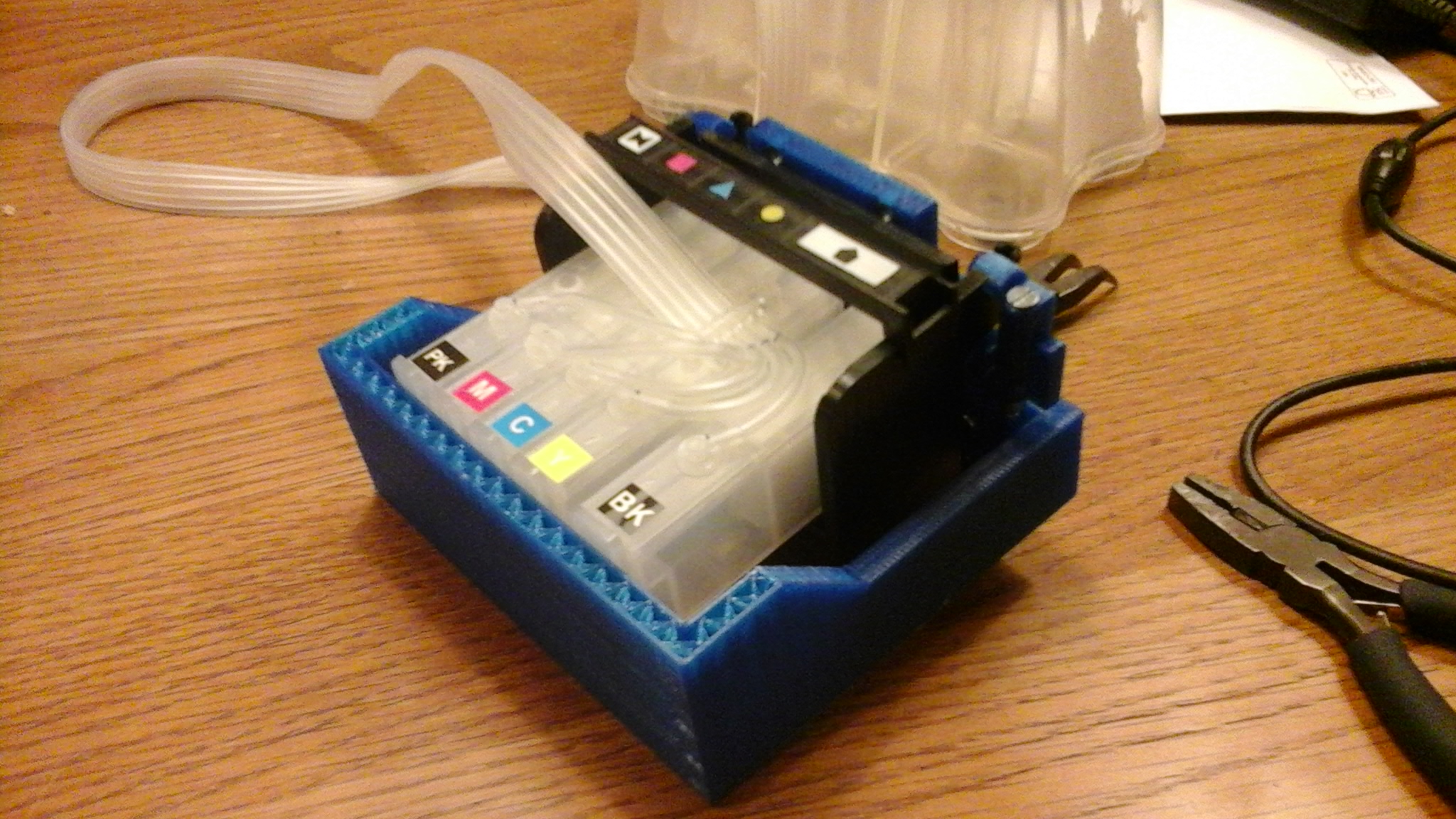
About a month ago I designed this cartridge holder as an addition for the carrier I already had. Then the UP! broke. I finally printed and tested it and I have to say, wow, I almost did it right on the first try. Cartridges press neatly into the rubber pads and the cartridges are firmly stuck in the holder. That is the only issue. They are stuck.
I will add 1mm to the front to give it just that tiny bit of clearance and round the top to make it easier.
@Wonko, great work. I don’t think my input will be of much help right here, but when I come up with something, I will tell so immediately.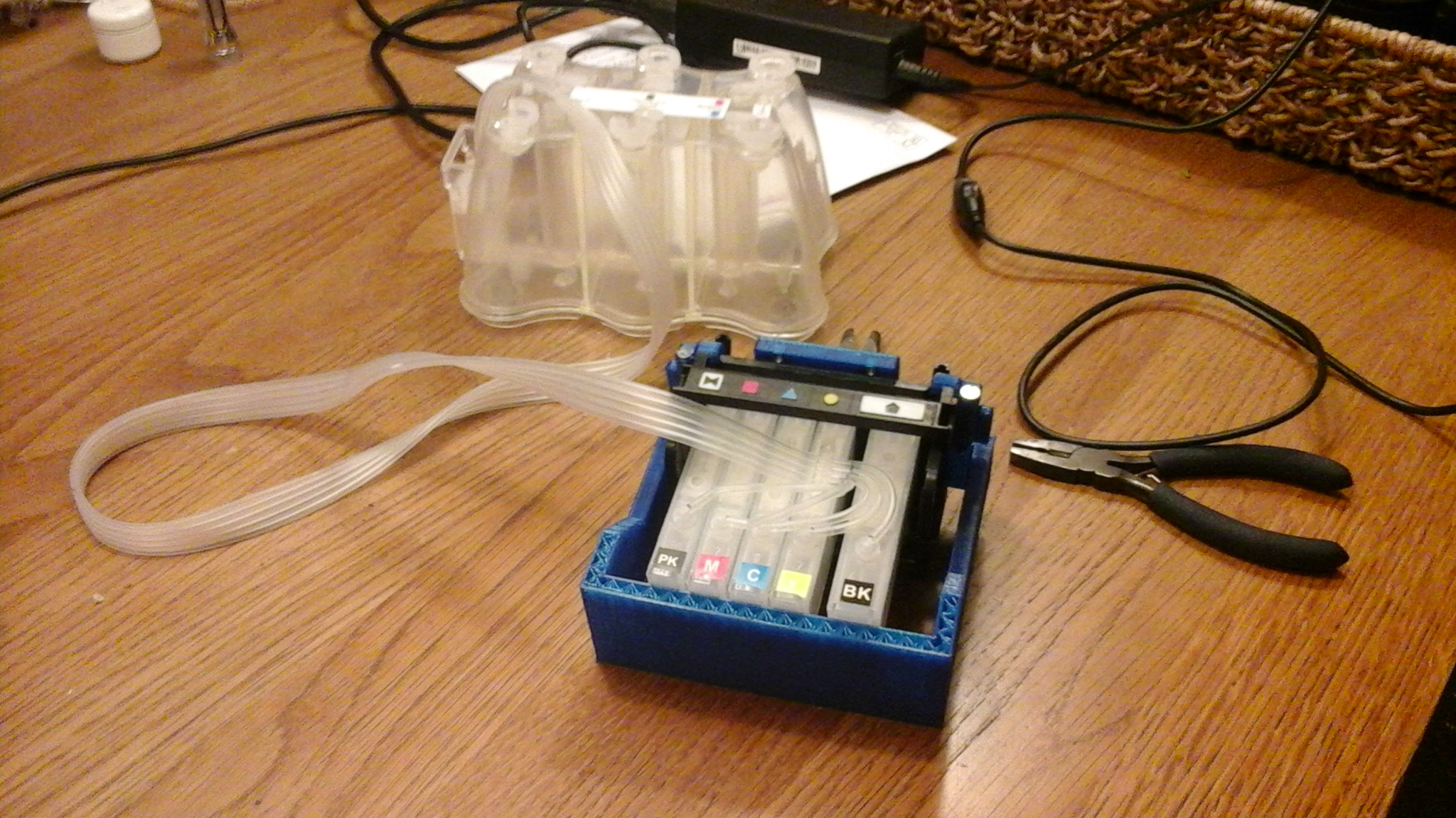
 November 4, 2014 at 9:28 pm #1987Participant
Looks great! This is perfect for simply mounting the head on a motion axis.
Does the CIS have a name or order number? I could not find it on the ‘net.
Some of the signals on the head confuse me. I really don’t know what the 1v +-0.5V signal levels are good for. I have not seen that on other devices before and I don;t see the advantage over the 3V signals. OTOH, I have purposefully not printed with any of the four photo cartridges. Maybe these levels are just some idle noise and pin 11 to 15 are the shift register for the large black tank?!
November 4, 2014 at 10:10 pm #1988KeymasterSimply googling ‘hp364 ciss’ will yield a lot of results. 364 is the cartridge number, 642 is the printhead number. Mine was bought here:
I will let some thinking time loose on your signal conundrum to see if I think of something.
November 4, 2014 at 11:34 pm #1989ParticipantNOTE: I did flip a few pins in the list above! 18, 19, and 20 are GND, 21, 22, and 23 run 32 Volts. As for 24, I do not know, but it may be 32V as well. That pin only leads to the black cartridge.
I also found a few articles on “band gap voltage generation”, which is a method to generate a temperature independent voltage at precisely 1.25V. One of the pins looks like it is a reference for the 32V lines to keep the print quality perfect (stab in the dark 😉
Lastly, after reading many patents, there is likely an ID chip on the ink head that is read by the printer, as well as temperature sensors. So there are likely lines that transfer data from the head to the controller.
November 6, 2014 at 4:26 am #1991ParticipantAny chance you can post screenshots of your scope captures anywhere?
Maybe the waveforms will ring a mental bell for me.
Are you capturing at the printhead (pen) itself, or the carriage, before the ASIC?
November 6, 2014 at 8:06 pm #1992ParticipantWell, it’s important to use the right tool for the job. Using my new Saleae, I found out MUCH more about the signals. The first finding is, that using a cheap scope will generate false signals and waste of time 😉
All signals are taken at the ribbon cable that leads right to the head, after any electronics. Here is a photograph of how the pins are mapped to head. Note that I defined the leftmost pin as 1. The printhead contacts are of course reversed, so the top right contact is 1 in my previous numbering. All further numbers refer to the ribbon wires!
 November 6, 2014 at 8:35 pm #1993Participant
OK, so let’s look at some wave forms. In the middle of printing a page of black-only text, I trace the signals for 10 seconds. The first image shows pin 1 to 8 (named 00 to 07 in the software). Pin 4, 5, 7, and 8 show a short spike every 1.5 secs. More on that later. Channel 5 shows blocks of pulses.

Now for a close-up on pin 4. The signal sits at 1.5V, is then pulled down for 12ms, then bounces to 3V for a very short time, and goes back to 1.5V.

Now for pin 6. This looks like a 0-3V clock signal at 66kHz. It comes in 5 or so bursts per Pin 4, 5, 7, 8 cycle. Printing a single line takes less than 1.5 seconds. It seems that instead one burst corresponds to one printed line.
 November 6, 2014 at 9:09 pm #1994Participant
Next block, lines 9 to 16 (00 to 07 in the screen shots). 10 and 16 exhibit the same three-level behavior as 4, 5, 7, and 8. None of them seem to carry any data besides the occasional sync.
9 seems to carry a lot of noise. It does not look like a true signal to me. It could be in trig-state mode with cross talk??
13 seems to be a short sync, but also seems to carry true data around the line 10/11 sync.
12, 14, and 15 are quite busy. 12 runs at about 6kHz, 14 at 300kHz, and 15 at 24kHz.
11 is a slow sync, going to 0V every 1.6 seconds.

On the logic side in a higher frequency, we can see a litte bit more:
 November 6, 2014 at 9:19 pm #1995Participant
Alright, so we are missing 17 which looks pretty much exactly like 10 and 16 and the others. 18, 19, and 20 are GND. 21, 22, and 23 carry 32V when needed, but since I do not have a voltage divider, I didn’t measure that. For line 24, I don’t know. It’s a wide line, so it carries some higher wattage. I’ll have to scope that again before using the logic analyses. I may well be logic GND.
November 6, 2014 at 9:24 pm #1996ParticipantPS: I would upload the analyses files, but they are 16GB a piece (yes, Gigabytes!)
-
AuthorPosts
- You must be logged in to reply to this topic.