(Edit 2024-01-21: The project development for this project and related HP45 control projects has stopped. The Teensy 3.5 that the project requires is no longer available, and I have stopped fully supporting this design. The way to control the printhead and testing circuitry can still be used for reference, but this project is not a finished project that you can replicate with the expectation that it will just work. Make at your own risk.)

Many electronics components come on a tape used for automated assembly. The cheaper components, mainly resistors and capacitors are in a paper tape that has no marking or indication what the component inside is. To prevent excessive searching and mixups, a way to clearly mark a tape with the component inside was sought.
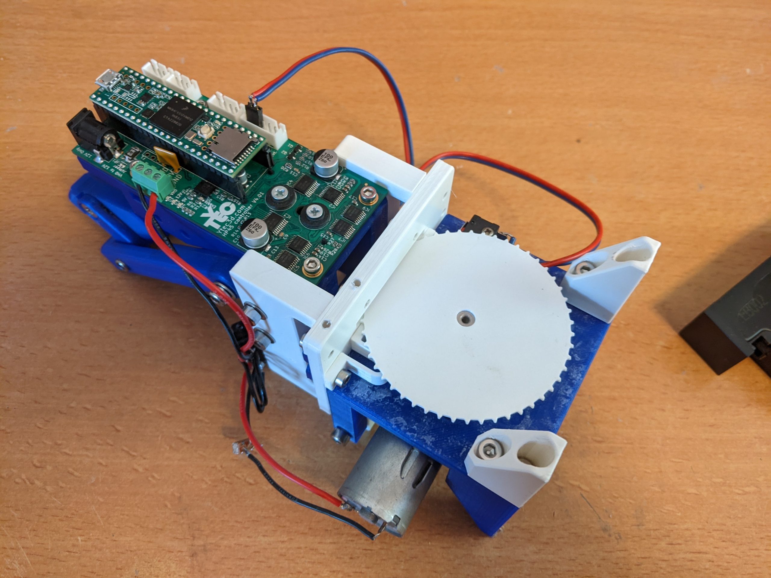
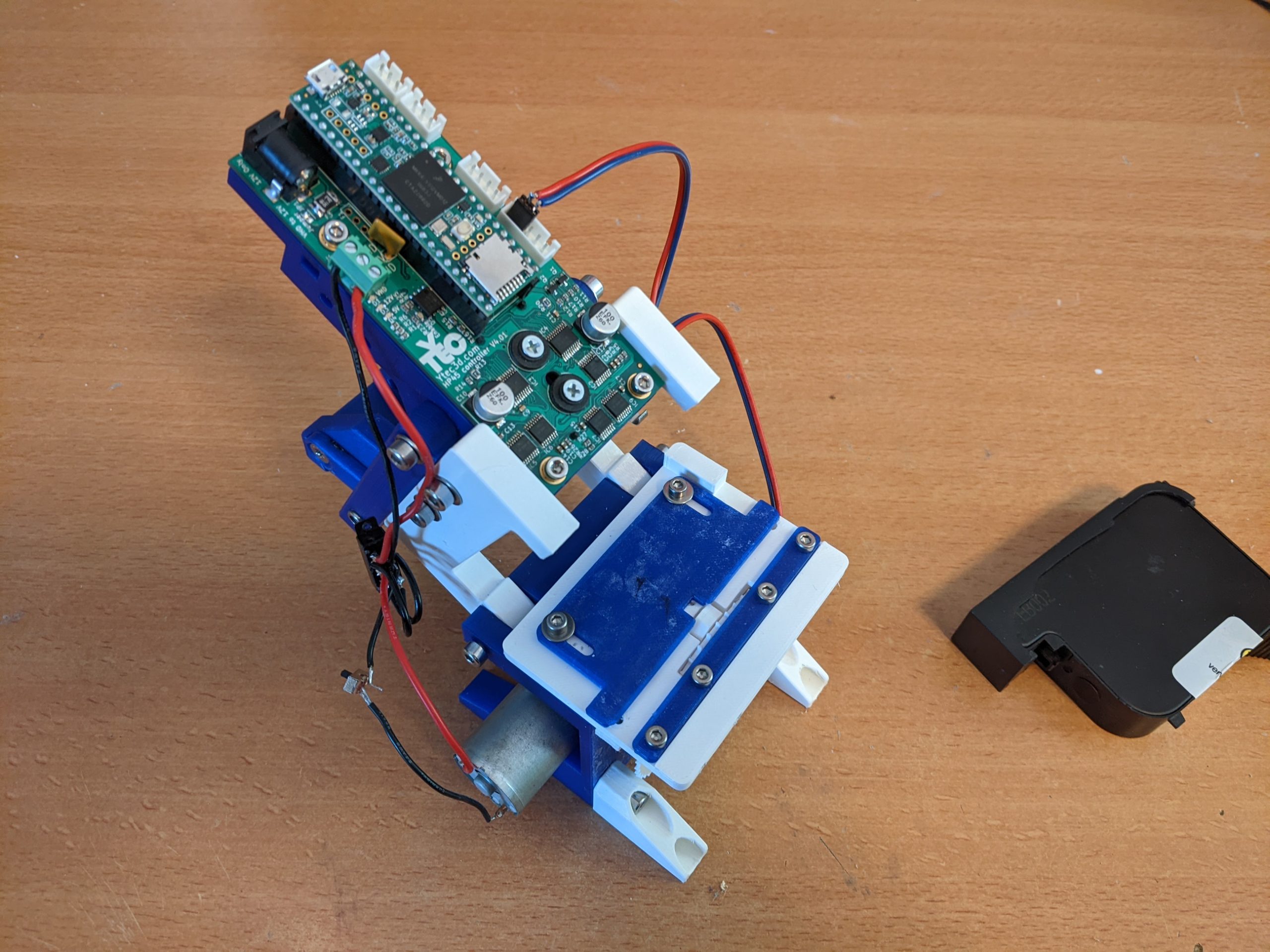
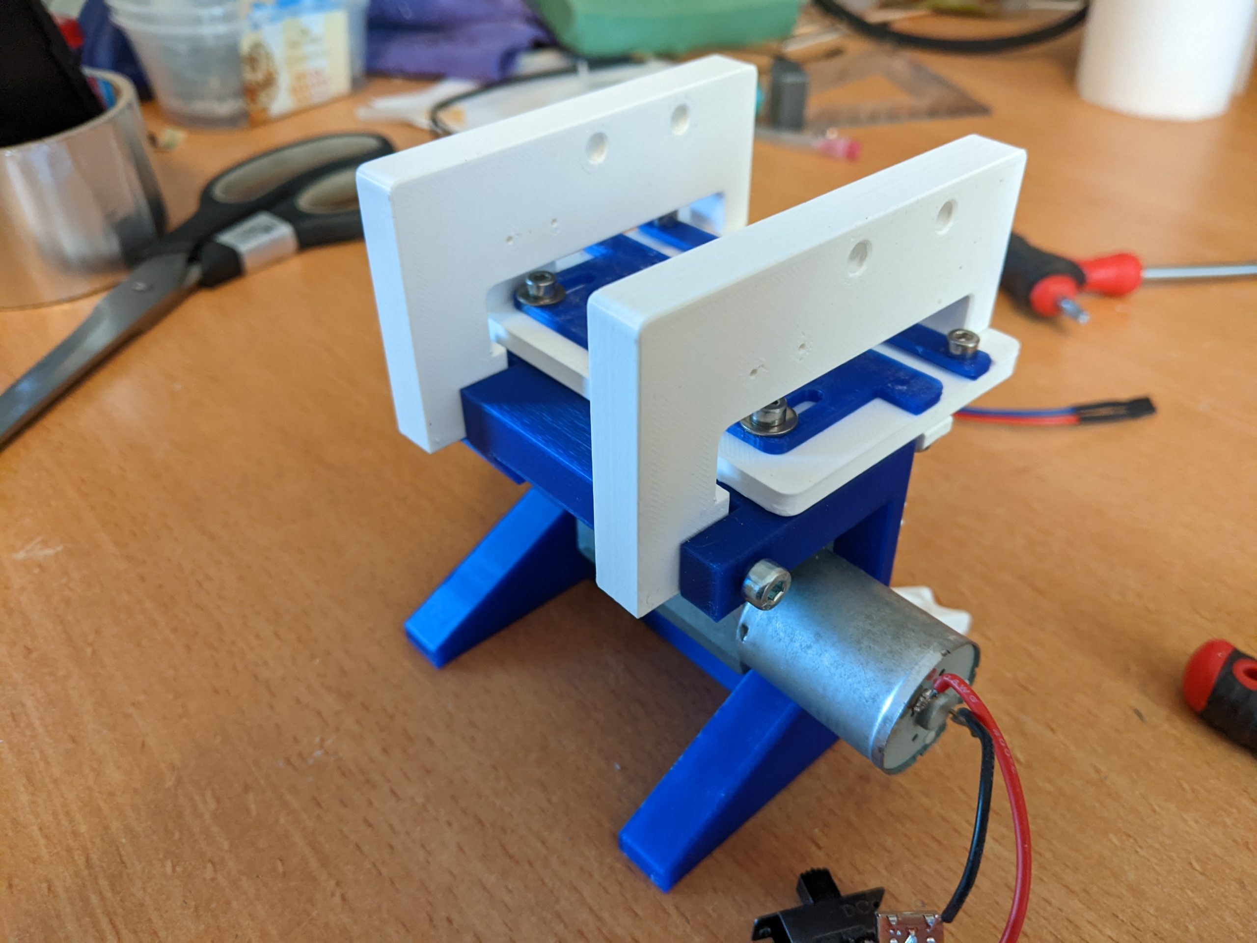
The SMD tape printer is used to print any image on the tape. In this case it is used to print an image of the component value on the tape. To do this a sprocket pulls the tape under an HP45 inkjet printhead that continuously prints the value while the tape is under it. A combination of two switches is used to determine if the printhead can print. One switch under the printhead determines if tape is present. For maintenance the printhead can be flipped away. A second switch determines that the printhead is in place.
The SMD tape printer example uses the following functions:
- Bitmap image printing
- Virtual velocity printing
- While high/low trigger
- Looping image printing
- Single sided printing
Used controller: HP45 standalone V4.01
Supported Firmware: V4.01.06 and higher
Operation
Preparing controller
Connect the controller to a 12V power supply of at least 3A. Connect the Teensy 3.5 to the computer using a micro usb cable. The computer should recognize the controller and assign it a COM port. If not, check if Teensyduino is installed. Insert an HP45 printhead into the controller.
Inkjet commander
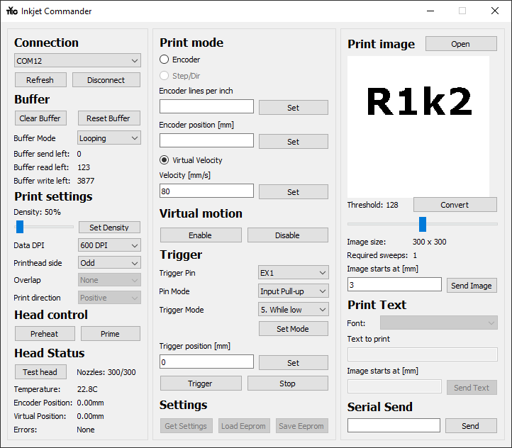
The operations will happen from top left to bottom right.
- Connection: Select the COM port for the HP45 controller. If you do not see it in the list click “Refresh”. If you have the selected the COM port, click “Connect”. The software will take a few seconds to establish a connection.
- Buffer:
- Press “Clear buffer” to make sure no data is left in the buffer.
- Set the “Buffer mode” to “Looping”. This will make the buffer go to 0 (the start of the image) when the whole image is printed and will reset the position to the “Trigger Position”.
- Print settings:
- Set the density to the desired value with the slider. In the example 50% was used.
- With a density selected, press “Set Density”. The percentage is how many drops of ink per inch are deposited per nozzle. 100% is 600, 50% is 300.
- Set the “Printhead Side” to “Odd” or “Even”. “Both” will make both rows of nozzles fire, which creates a blurry image if the speed is not exactly right.
- Print mode:
- Click “Virtual Velocity” to activate it. Virtual velocity means that the printhead will “move” at a given speed virtually. This movement only happens after a trigger.
- In “Velocity [mm/s]” set the velocity to the rough speed of the tape in mm/s. Write an integer of the speed in the field and click “Set”.
- Virtual motion: Press “Enable” to enable the virtual motion. Without this, no trigger will start virtual movement.
- Trigger:
- Select the used “Trigger Pin” in the drop down menu. In the example “EX1” is used, but any pin can be used. This is the pin all the following setting will apply to if the button “Set Mode” is pressed.
- Set “Pin Mode” to “Input Pull-up”. This will apply a pull-up resistor to the given pin.
- Set “Trigger Mode” to “5. While low”. This means printing will only happen while the trigger pin is low. If the buffer is looping it will also automatically set the position back to the “Trigger position [mm]” when the buffer reaches it’s end.
- Press “Set Mode” to apply all settings to the given pin.
- Trigger Position: Write the integer value of the position you want the printhead to go to when triggered in the field. In this example 0mm is used. Press “Set” when to set this position.
- Print image:
- Press “Open” to open a bitmap image. PNG, BMP and JPEG are allowed formats. An example of a working image is provided, as well as the GIMP file to modify yourself.
- Press “Convert” to process the image so it can be printed. In the window a preview will appear of the image. All the dark bits of the image are printed, al the light bits are ignored.
- If this image is not correct, slide the “Threshold” slide to alter the cut-off point between bright and dark.
- In the box under “Image starts at [mm]”, write the integer value of where the image starts. Due to how the printhead is shaped, a value of 3mm is used. Values smaller than 2.1mm may give issues depending on the side chosen.
- Press “Send Image” to write the image into the buffer. The value in “Buffer read left” Should now rise.
The controller is now ready to print. Then the EX1 pin is pulled to ground, it will become low and the printhead will trigger. This will reset the position to 0mm, and will reset the buffer to position 0. It will then print the image according the the position. When the last line in the buffer is printed, the buffer will reset itself and the position will flip back to 0, where the image will be printed again.
Clean printhead

Clean the printhead with a damp paper towel. Make sure all excess ink is removed from the printhead and that all nozzles have ink in them.
Starting motor
Flip the switch to start the motor. The direction seen in the video will print an unmirrored image. Printing in the other direction will require the mirroring of the image before printing it.
printing
With the head lowered onto the print area, the motor running and the controller prepared the tape can be fed into the printer. Once the tape is grabbed by the sprocket it is pulled through the printer. The tape actuates the switch which tells the printhead to start printing an image. It will repeat printing this image until the switch is released.
You can also stop the printing by raising the printhead itself.
Making one
Required components
- 1x HP45 standalone V4 controller
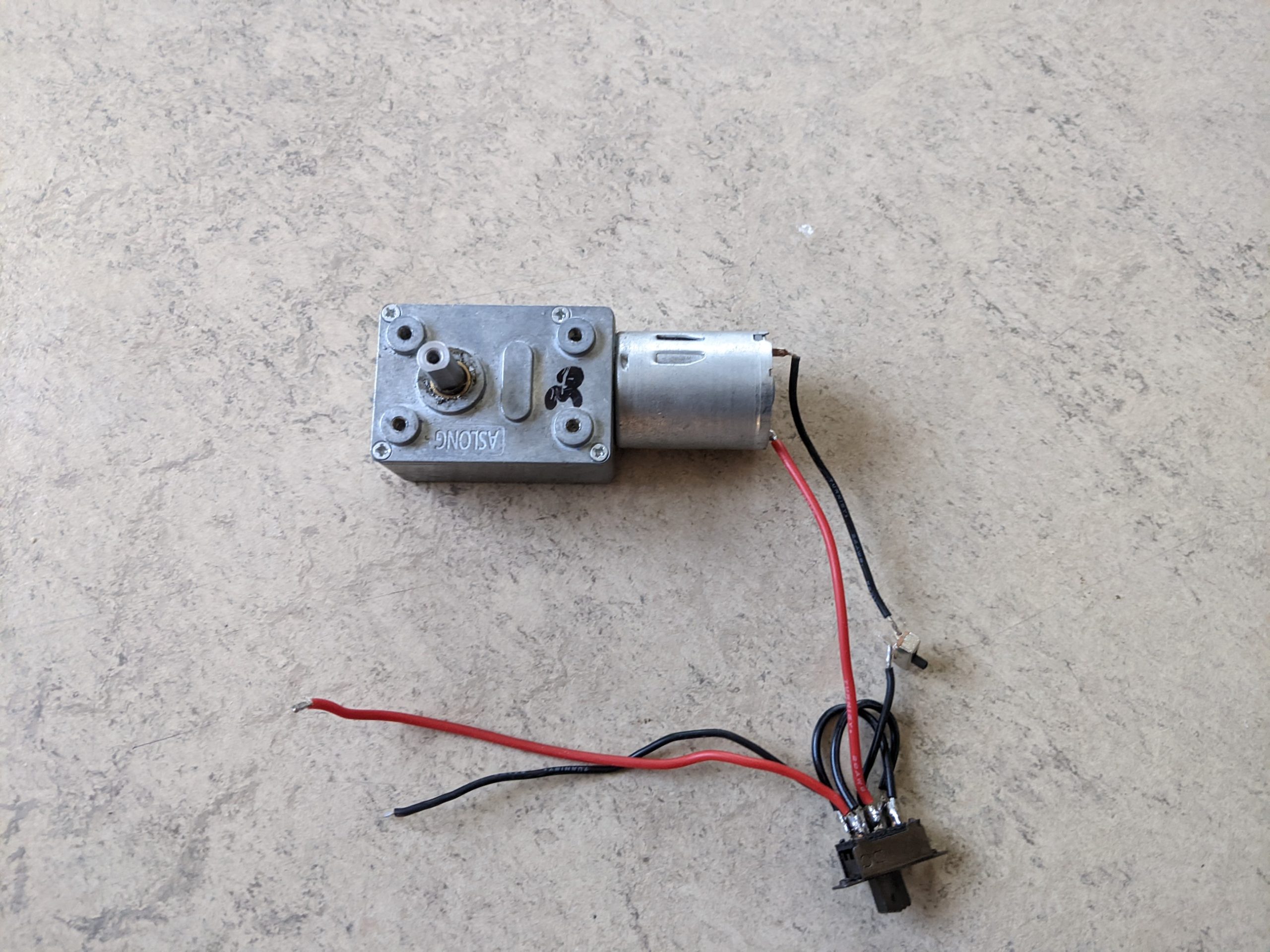
- 1x GW370 12V 30-60RPM Worm gear motor
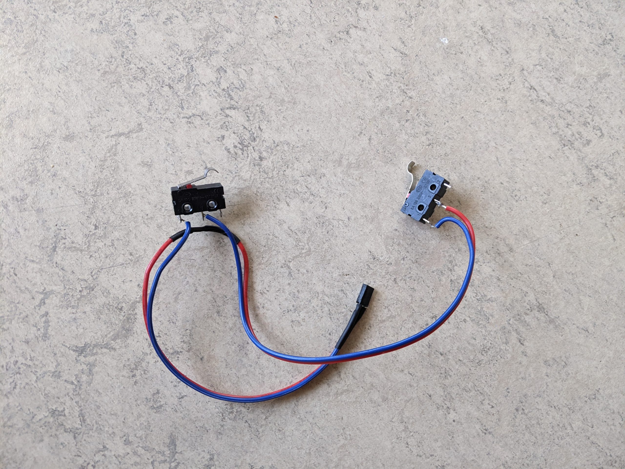
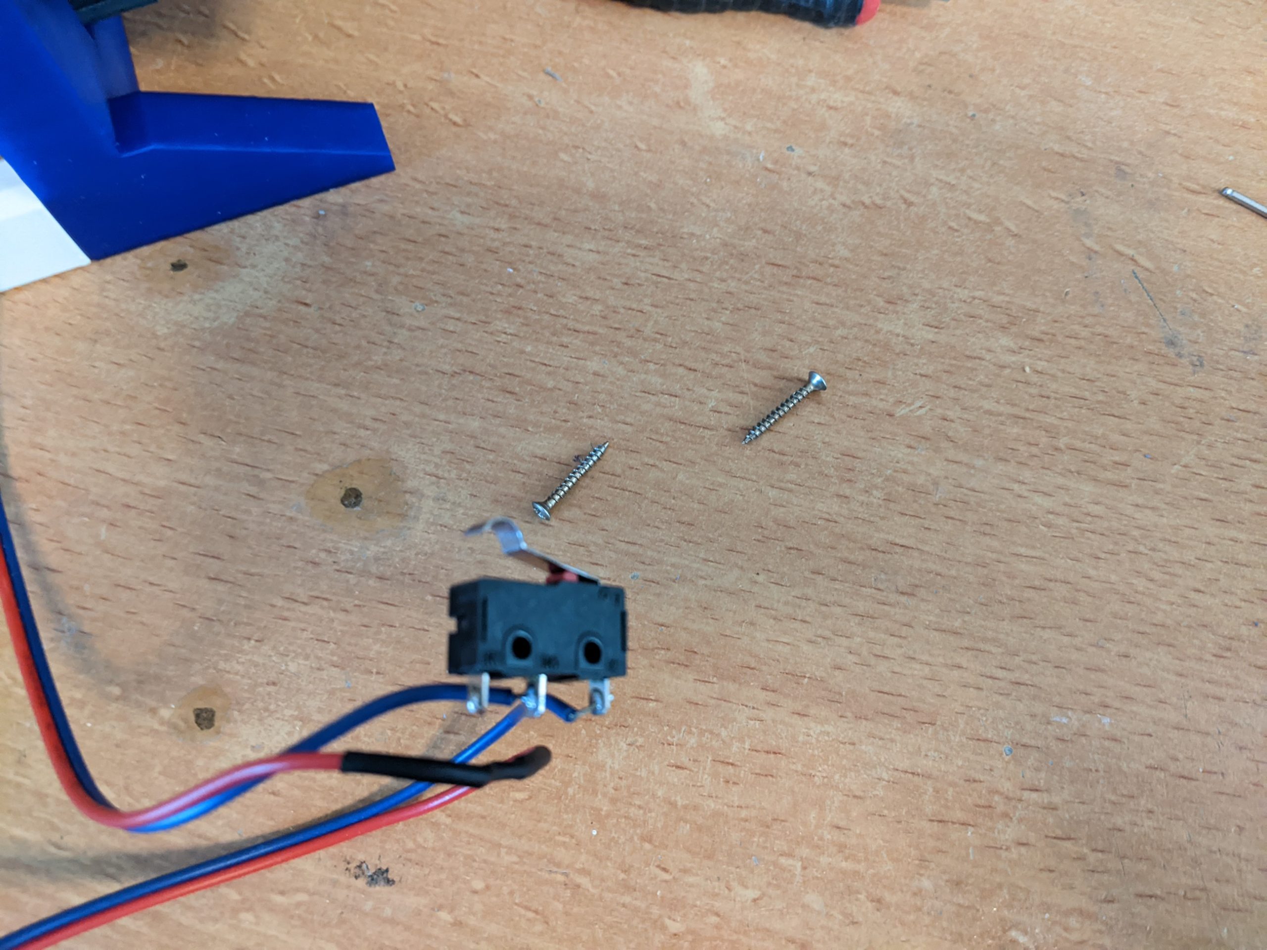
- 2x Omron 5e4t85 microswitch
- 1x 3 way double tact switch
- Flexible wiring
- 2x M3 ISO 9021 (fender washer)
- 4x M4 DIN 125 (washer)
- 11x M3x6 DIN 912 (Hex socket head cap screw)
- 2x M3x10 DIN 912 (Hex socket head cap screw)
- 4x M4x16 DIN 912 (Hex socket head cap screw)
- 4x M4x20 DIN 912 (Hex socket head cap screw)
- 2x M4x25 DIN 912 (Hex socket head cap screw)
- 2x M4x16 DIN 7991 (countersunk socket head cap screw)
- 2x M3 DIN 934 (nut)
- 4x M4 DIN 985 (Nyloc nut)
- 4x 2.0x16mm Universal screw

Downloads
The files for the tape printer can be downloaded by pressing the button below. In the downloads are the 3D printer files, a BOM, the schematic of the wiring, examples for common tape values and the STEP file for the tape printer.

3D printing
The tape printer uses several 3D printed components. For the example the components were printed at a layer height of 0.2mm and a nozzle diameter of 0.4mm. The parts were printed on a combination of a Prusa Mk2S and a Prusa Mini+. All parts are oriented correctly and designed for supportless printing. Some M3 and M4 screws tap into the plastic directly.
One tape printer has the following components (the quantity is in the file name):
- TP-P11-00 1x (sprocket)
- TP-P13-00 1x (trigger)
- TP-P14-00 2x (legs)
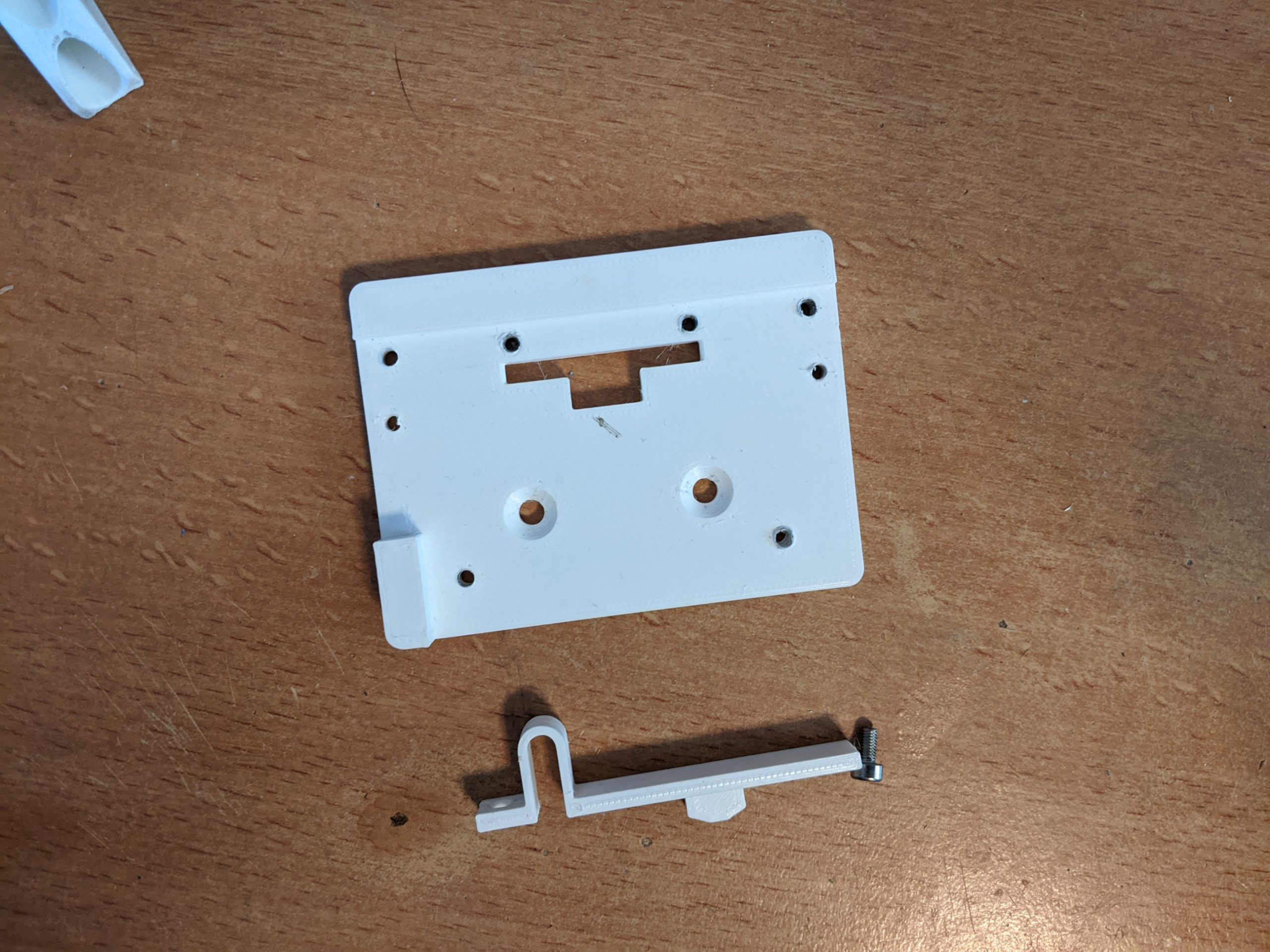
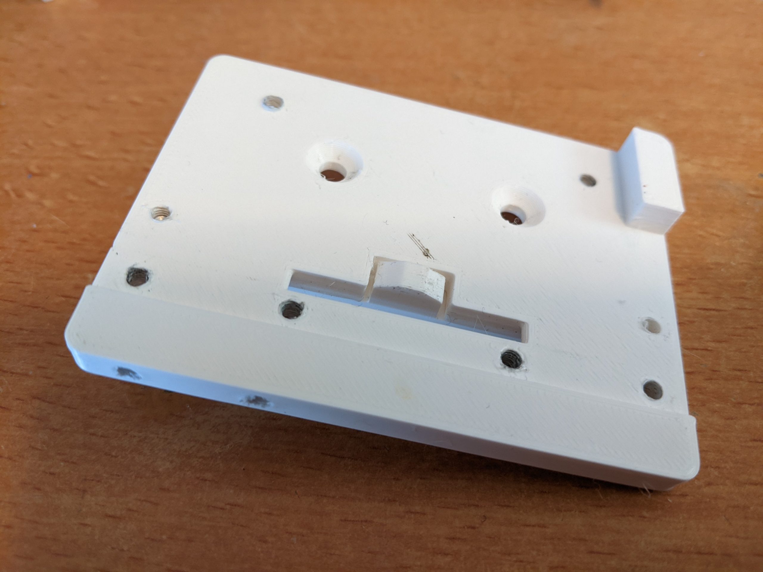
- TP-P16-00 1x (top plate)
- TP-P17-00 2x (hinge)
- TP-P18-00 1x (small fence)
- TP-P19-00 1x (large fence)
- TP-P20-00 1x (base)(4x 3mm holes need to be drilled after printing)

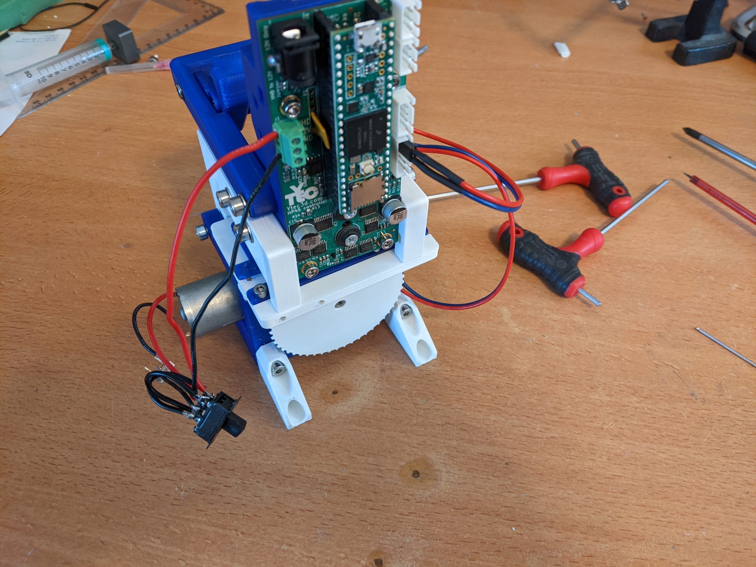
Mechanical assembly
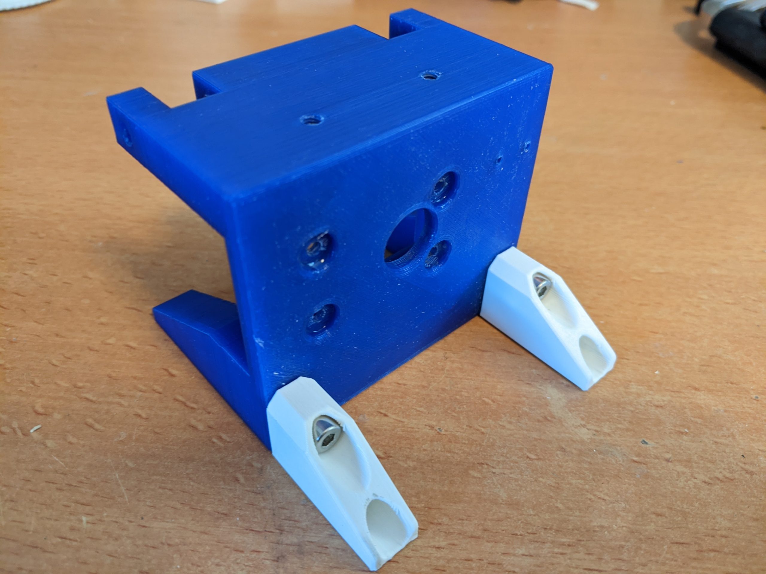
Base
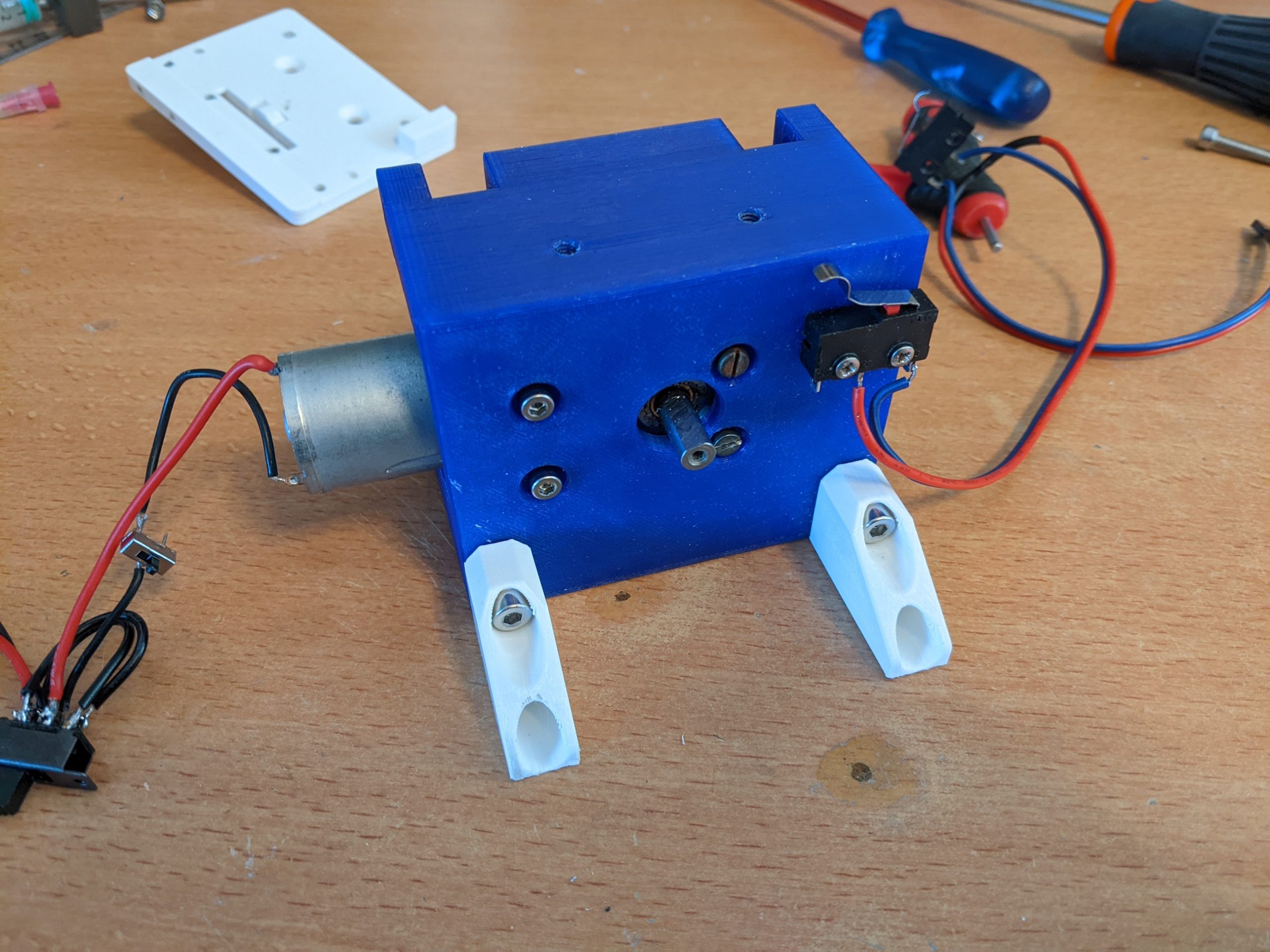
Start with the base (TP-P20-00). The 4 holes that will take the motor need to be drilled with a 3mm drill from the motor side.
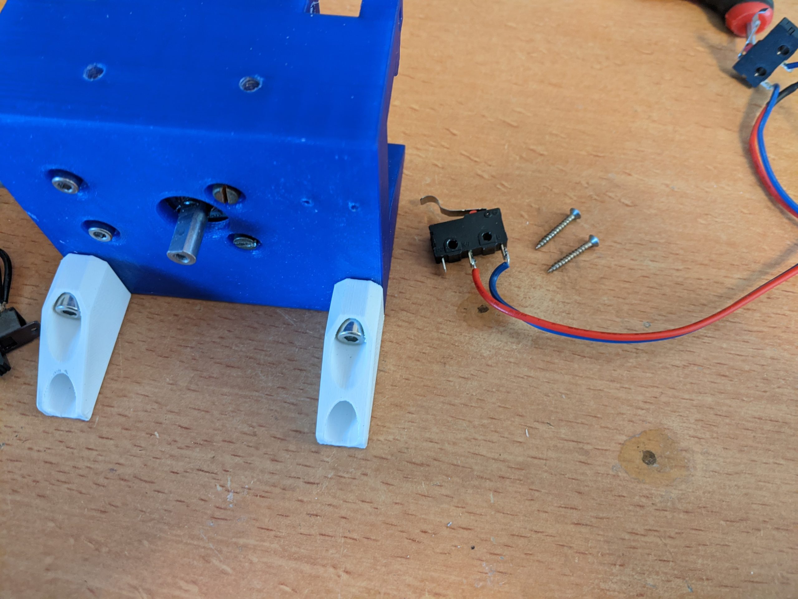
Take the 2 legs (TP-P14-00) and 4 screws (DIN912 M4x16). With a 3mm allen key mount the screws to the base. The screws need to tap their own thread, so it might take some force. To aid this you can tap the holes with M4 before mounting.
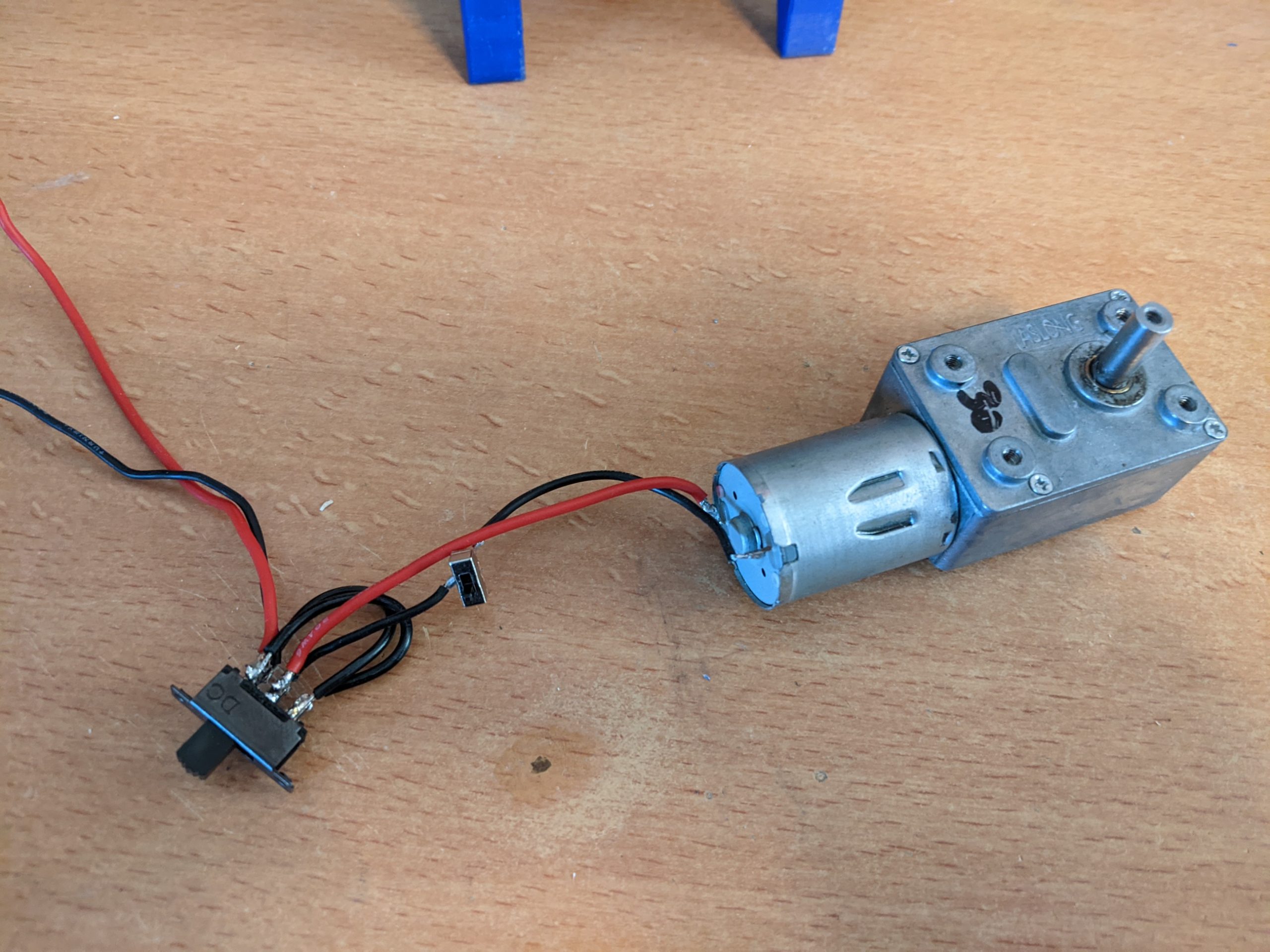
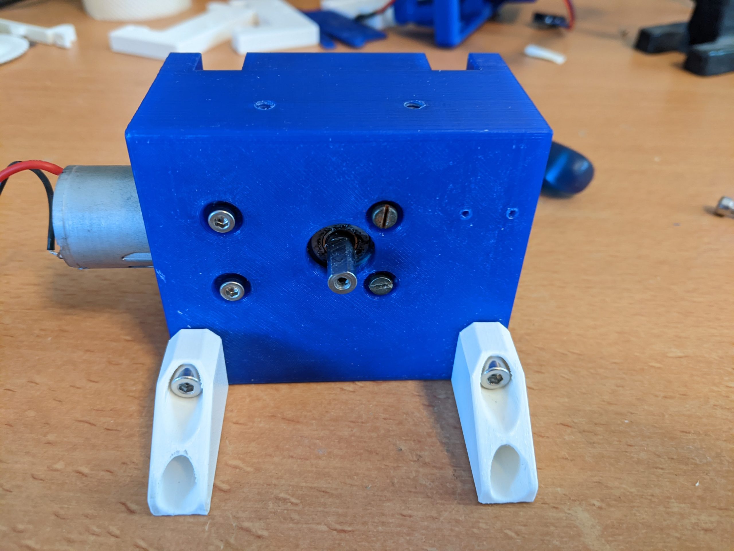
Mount the motor using 4 screws (DIN912 M3x6mm). The motor should only fit one way. The cable and switches can be added after the motor is mounted. The type of switch used is different from what is advised. Here 2 on-on switches are used, one for turning the motor on and off, and the other for changing it’s direction.

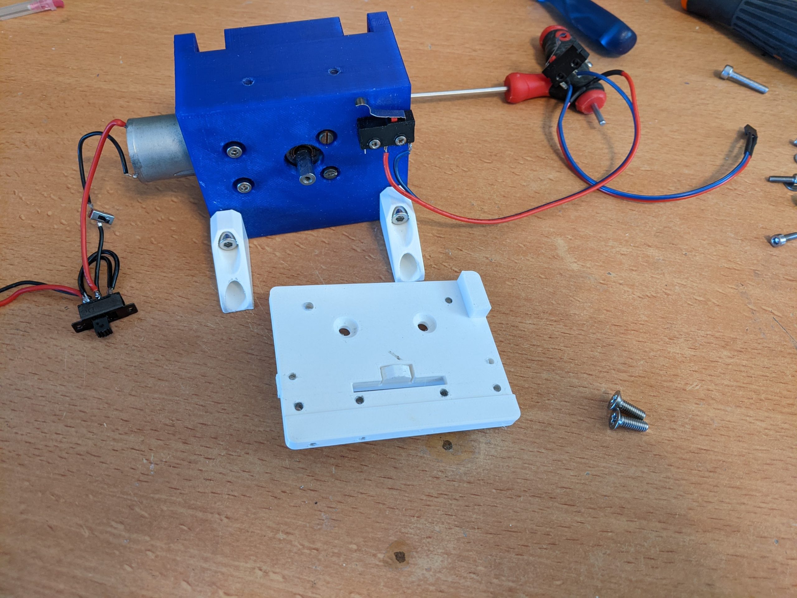
Top plate
Assemble the trigger to the top plate. This uses the top plate (TP-16-00), the trigger (TP-P13-00) and an M3 screw (DIN912 M3x6). Mount the trigger as shown, making sure it does not rub against any side of the top plate. The M3 screw needs to cut it’s own threads in the hole.
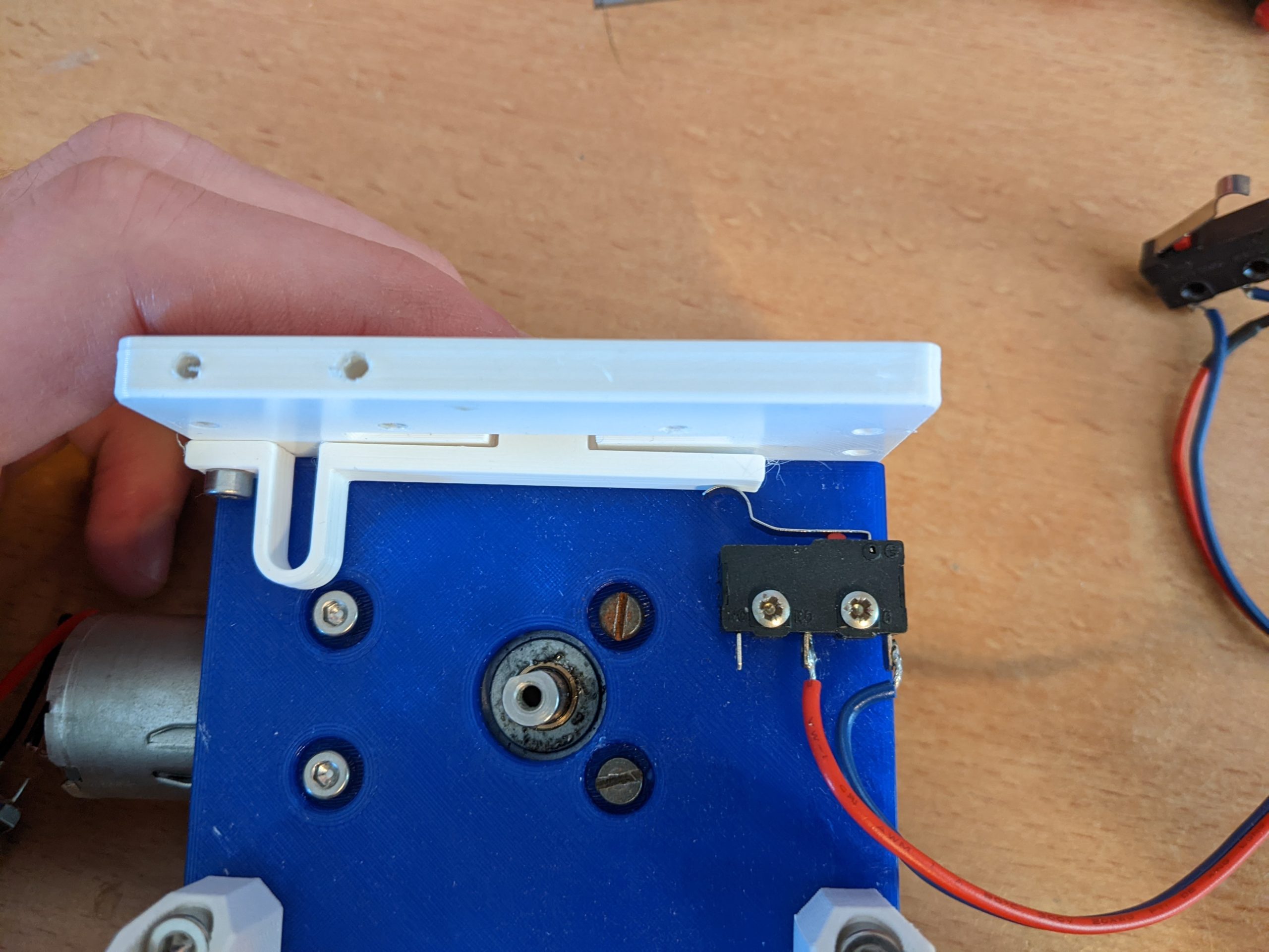
Mount the microswitch (5e4t85) to the base using 2 universal screws (2.0x16mm). The screws need to cut their own threads.
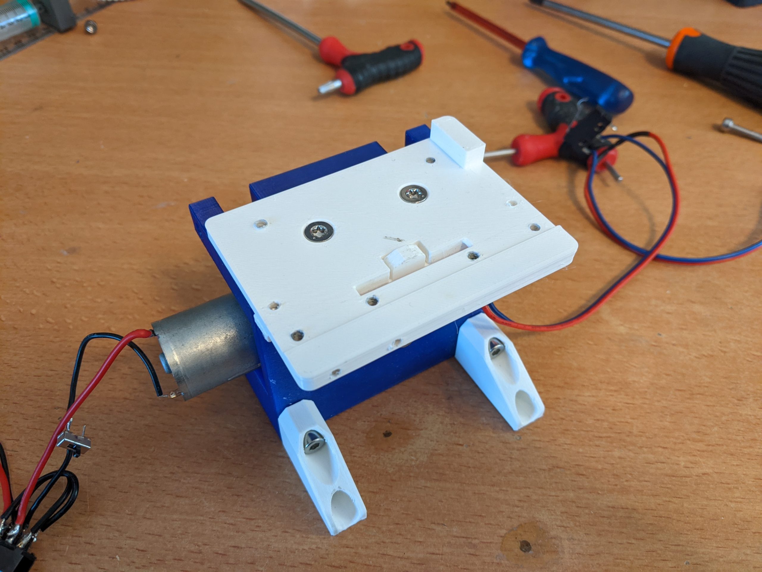
Mount the top plate to the base using 2 countersunk screws (DIN7991 M4x16). The screws need to cut their own threads.
The microswitch can be adjusted by bending the metal lever arm of the switch. The switch needs to trigger with the slightest movement, but needs to switch back when the trigger is released. The top plate may need to be removed for the smaller adjustments.

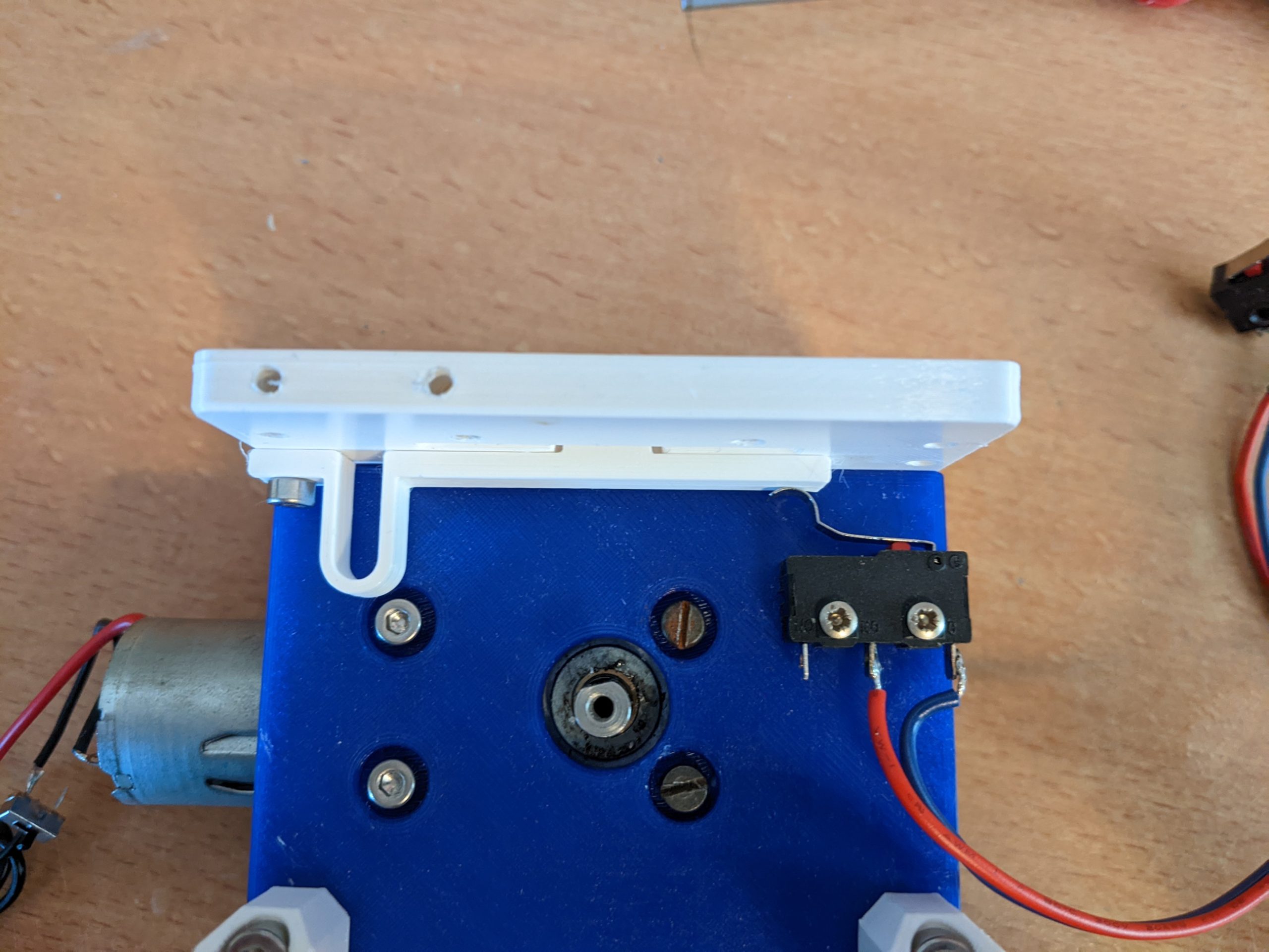
Sprocket
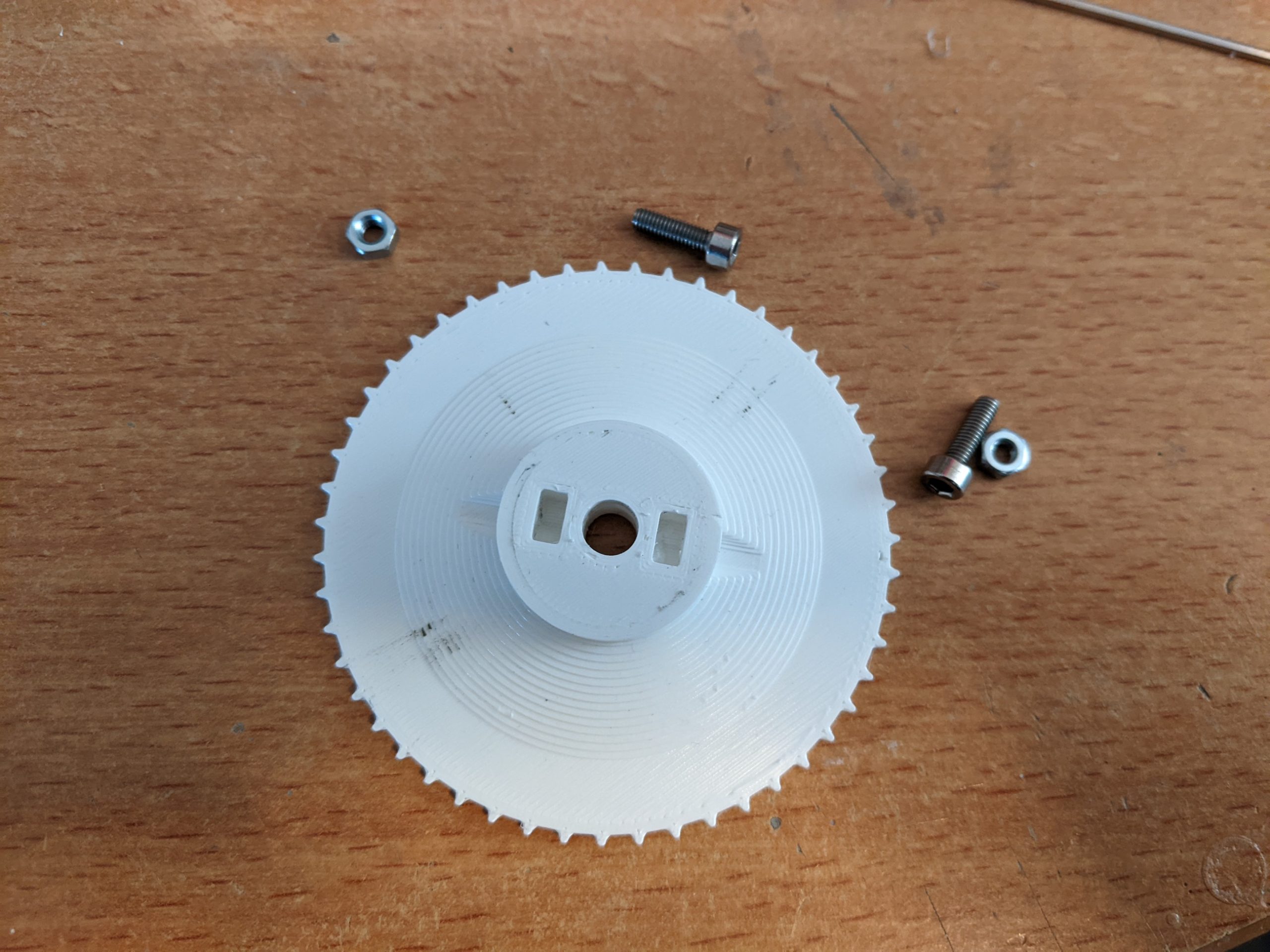
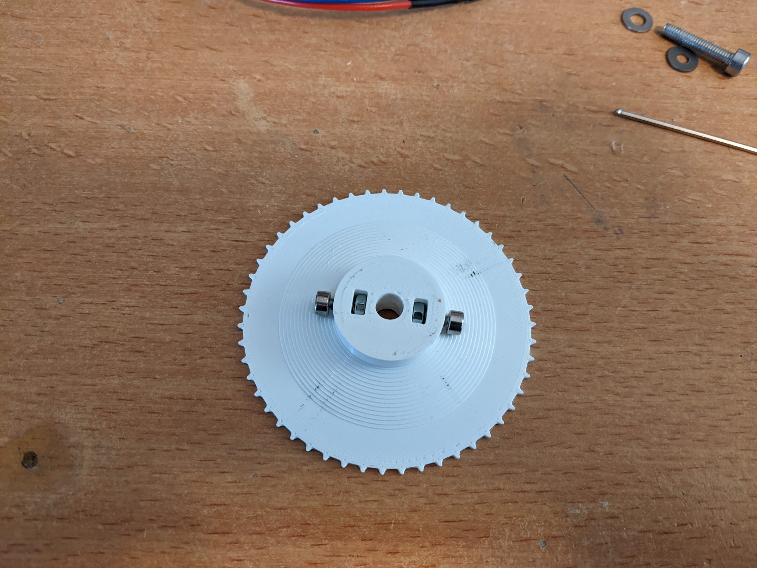
Assemble the sprocket (TP-P11-00) by inserting 2 nuts (DIN934 M3) in the rectangular holes. insert 2 screws (DIN912 M3x10), 1 in each nut as shown. Make sure the screws do not move into the hole for the motor shaft.
Remove the top plate from the base. Slide the sprocket onto the motor shaft, making sure at least one of the flats on the motor aligns with a screw. Do a test fit with the top plate to make sure the sprocket is roughly in the middle of the slot. If this is the case mount the top plate back on the base.

Fences
The fences hold the tape in place while it is fed and printed.
The small fence (TP-P18-00) is mounted to the top plate as shown using 4 M3 screws (DIN912 M3x6). The screws need to cut their own threads.
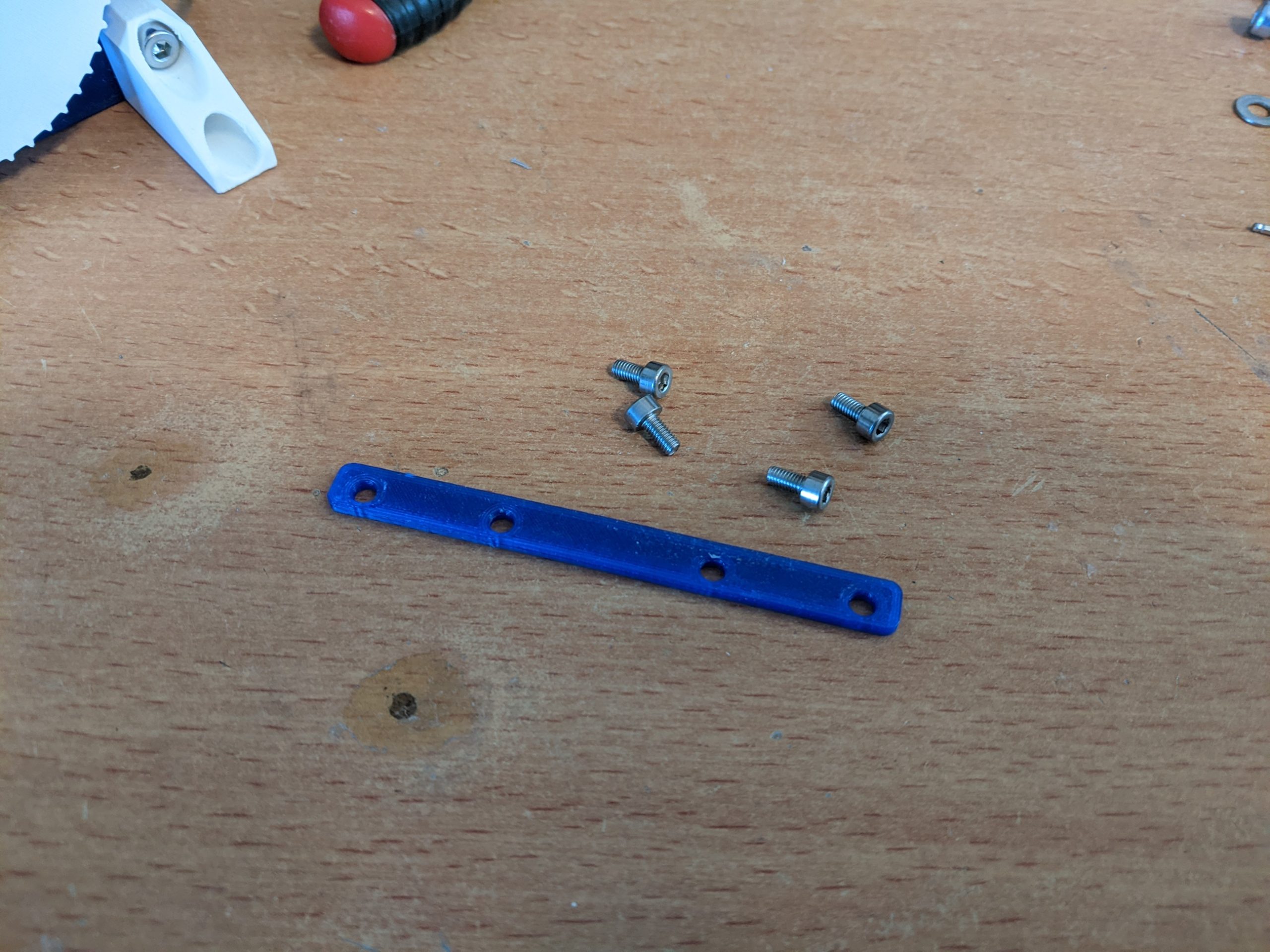
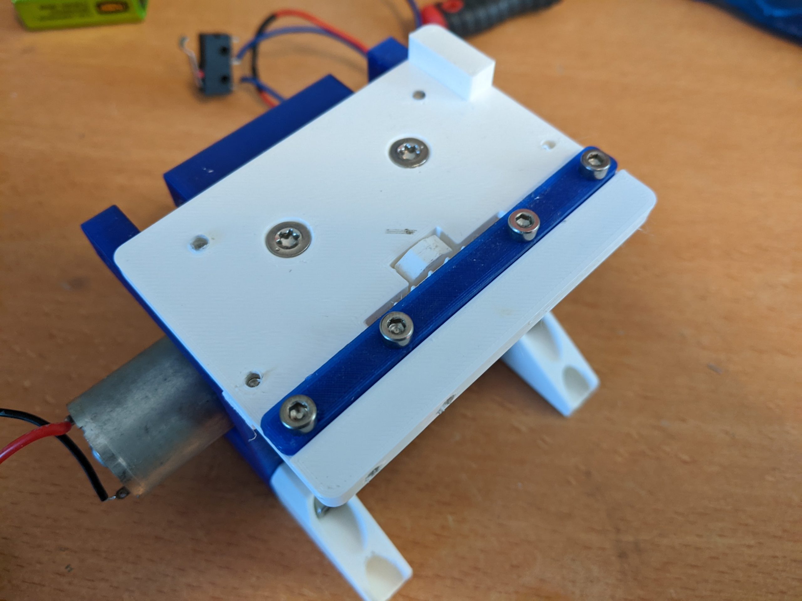
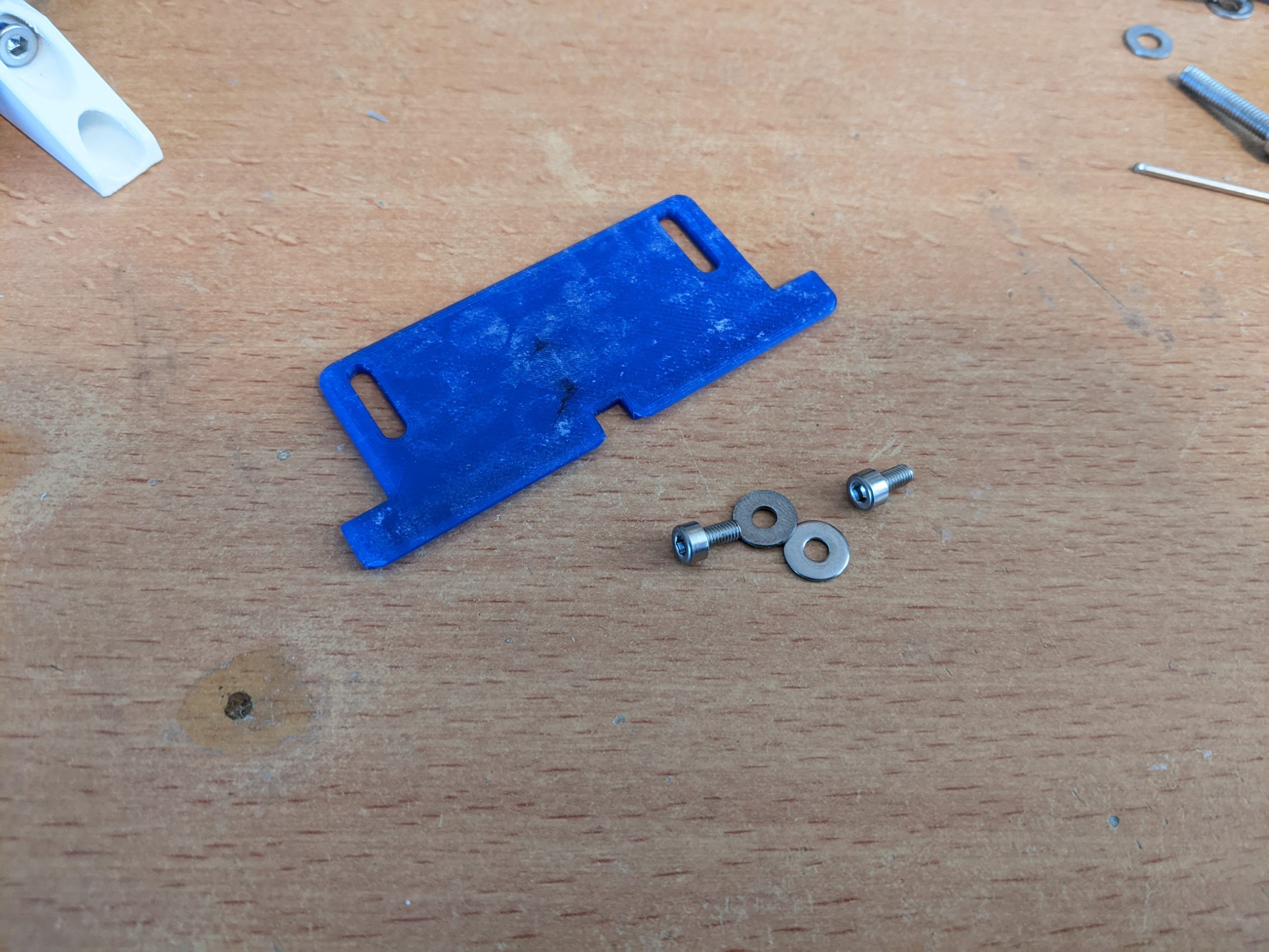
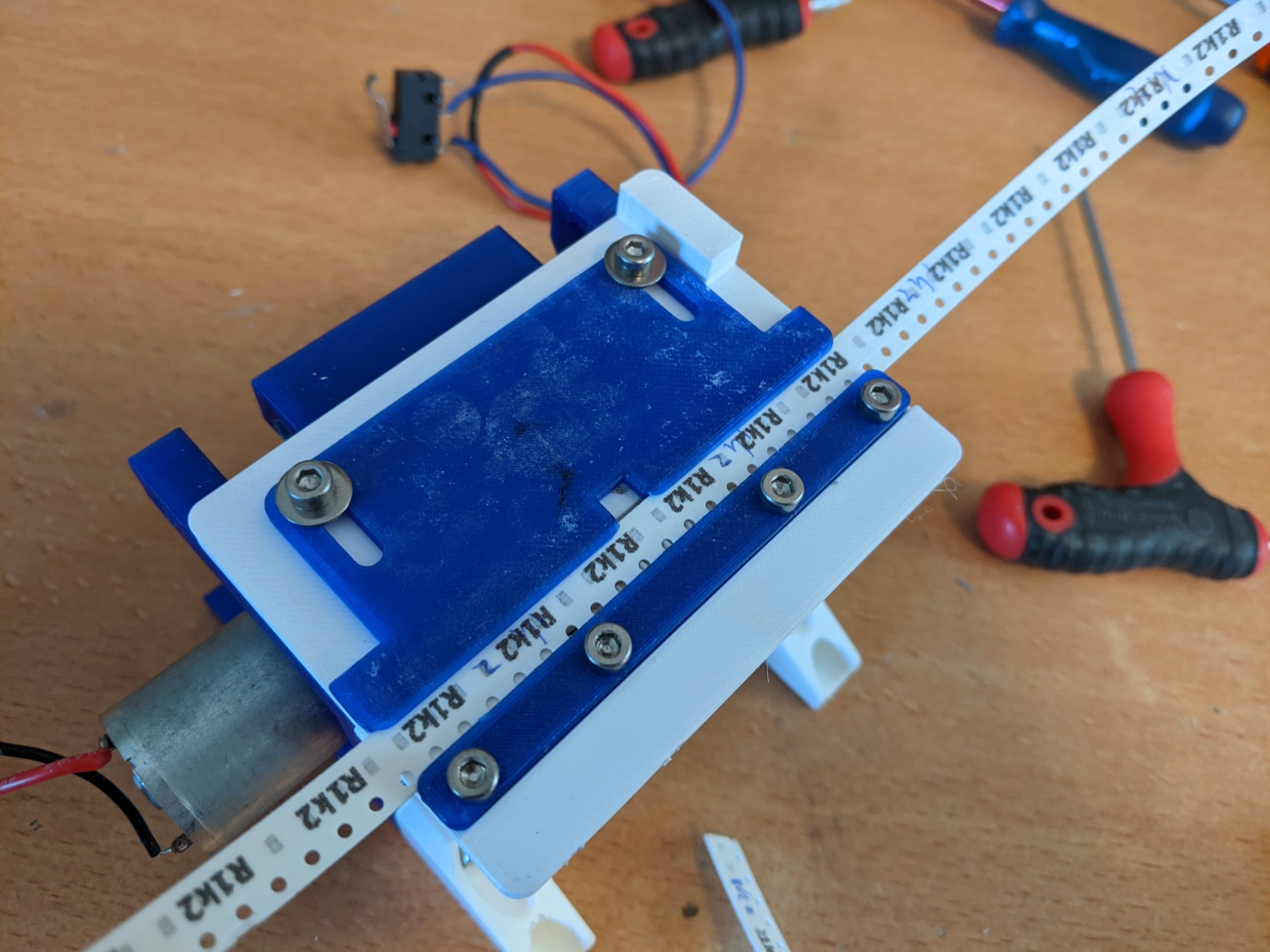
The large fence (TP-P19-00) is mounted to the top plate with 2 M3 screws (DIN912 M3x6) with 2 fender washers (ISO9021 M3). The screws need to cut their own threads. Do not tighten the screws as the fence still need to be adjusted.
Feed a tape between the fences. The holes facing the sprocket, and the plastic of the tape facing down. Slide the large fence towards the small fence until the tape is fixed in place but not
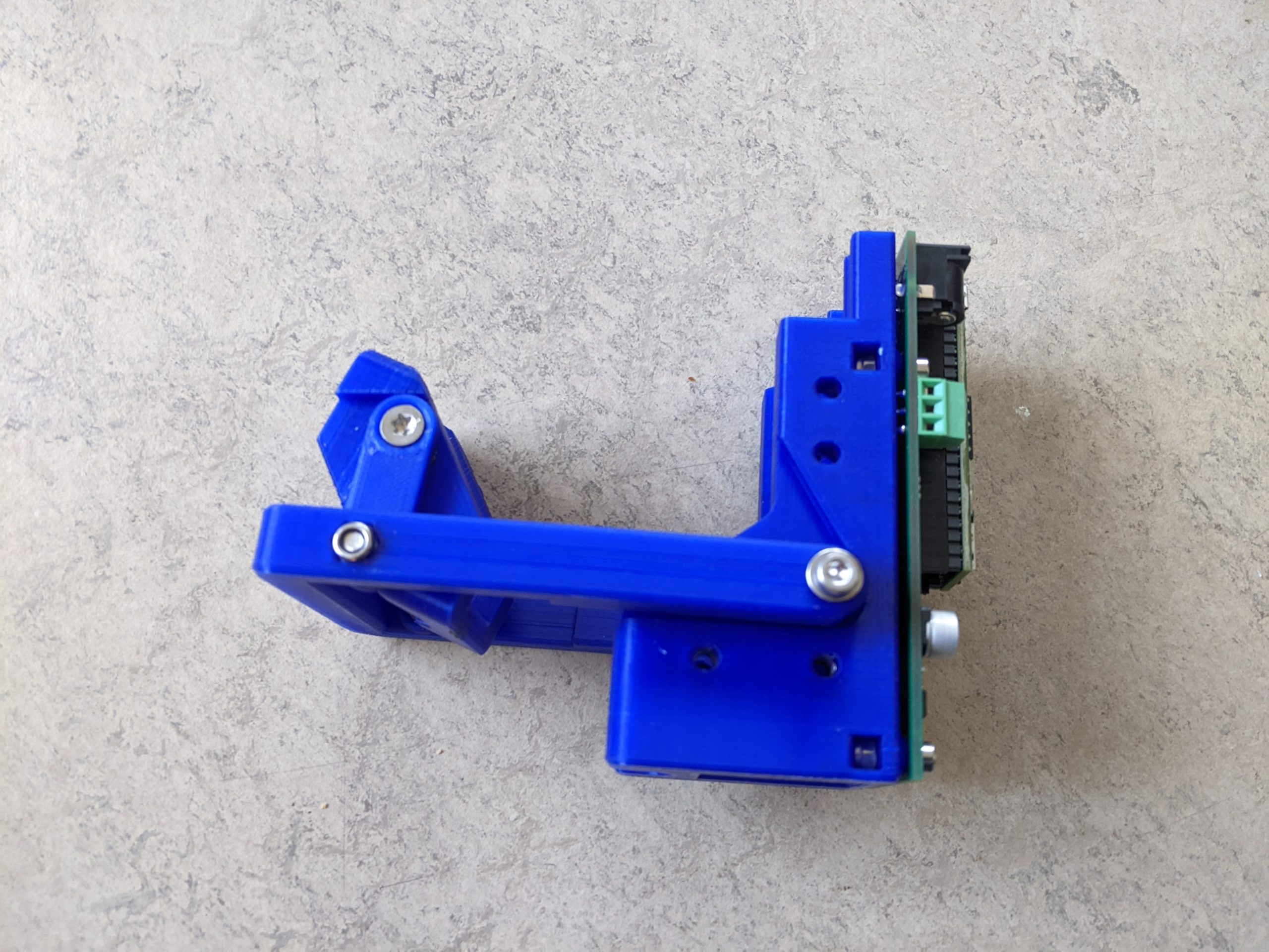
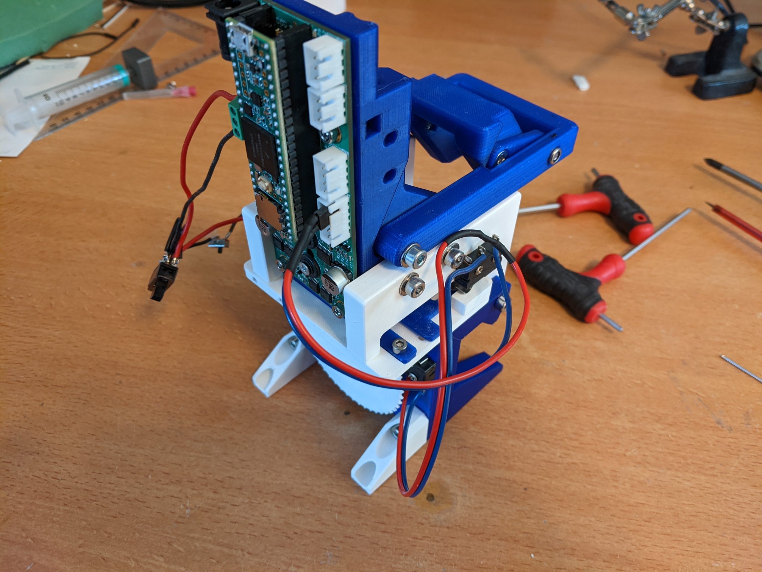
Inkjet
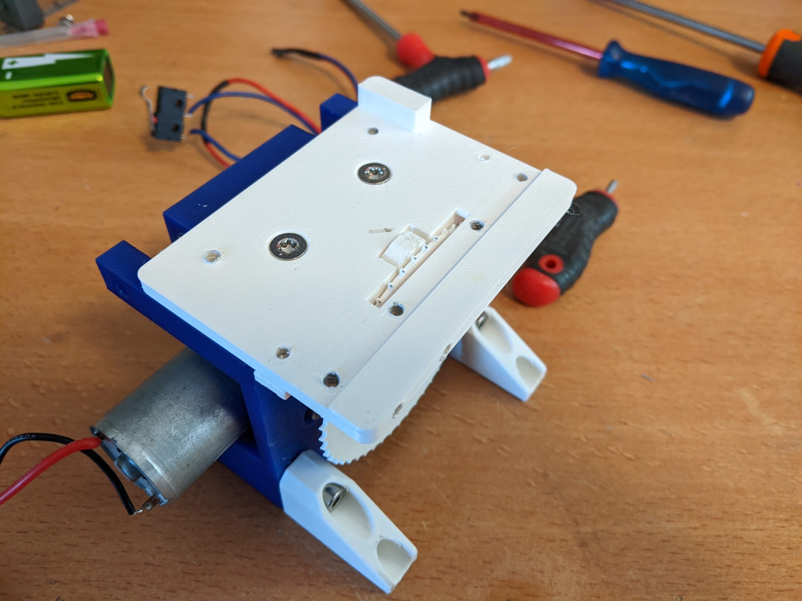
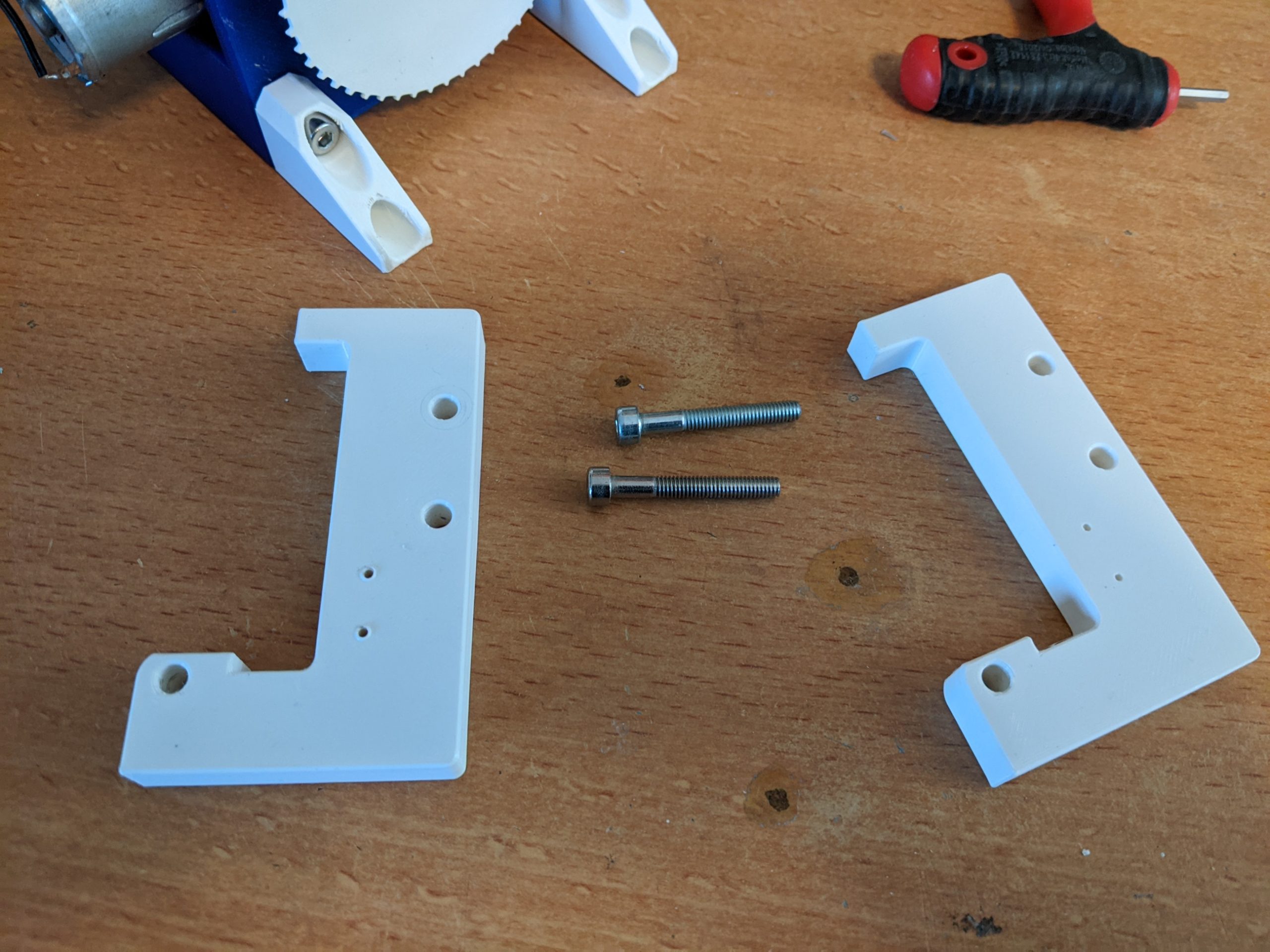
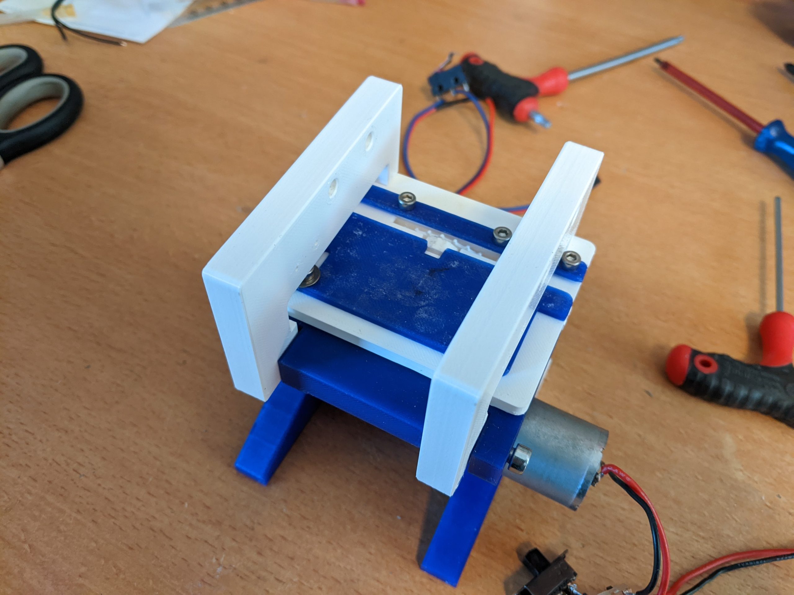
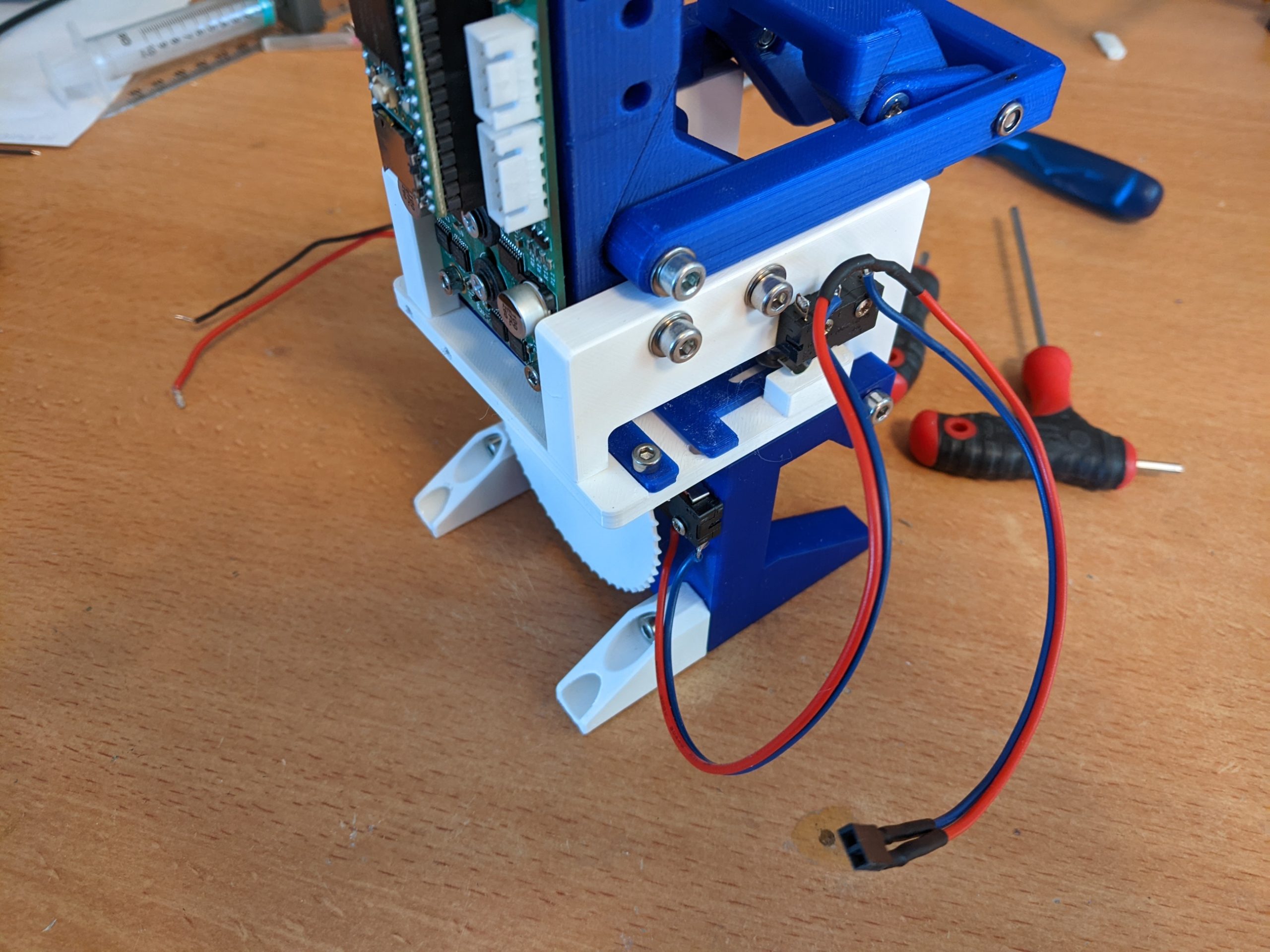
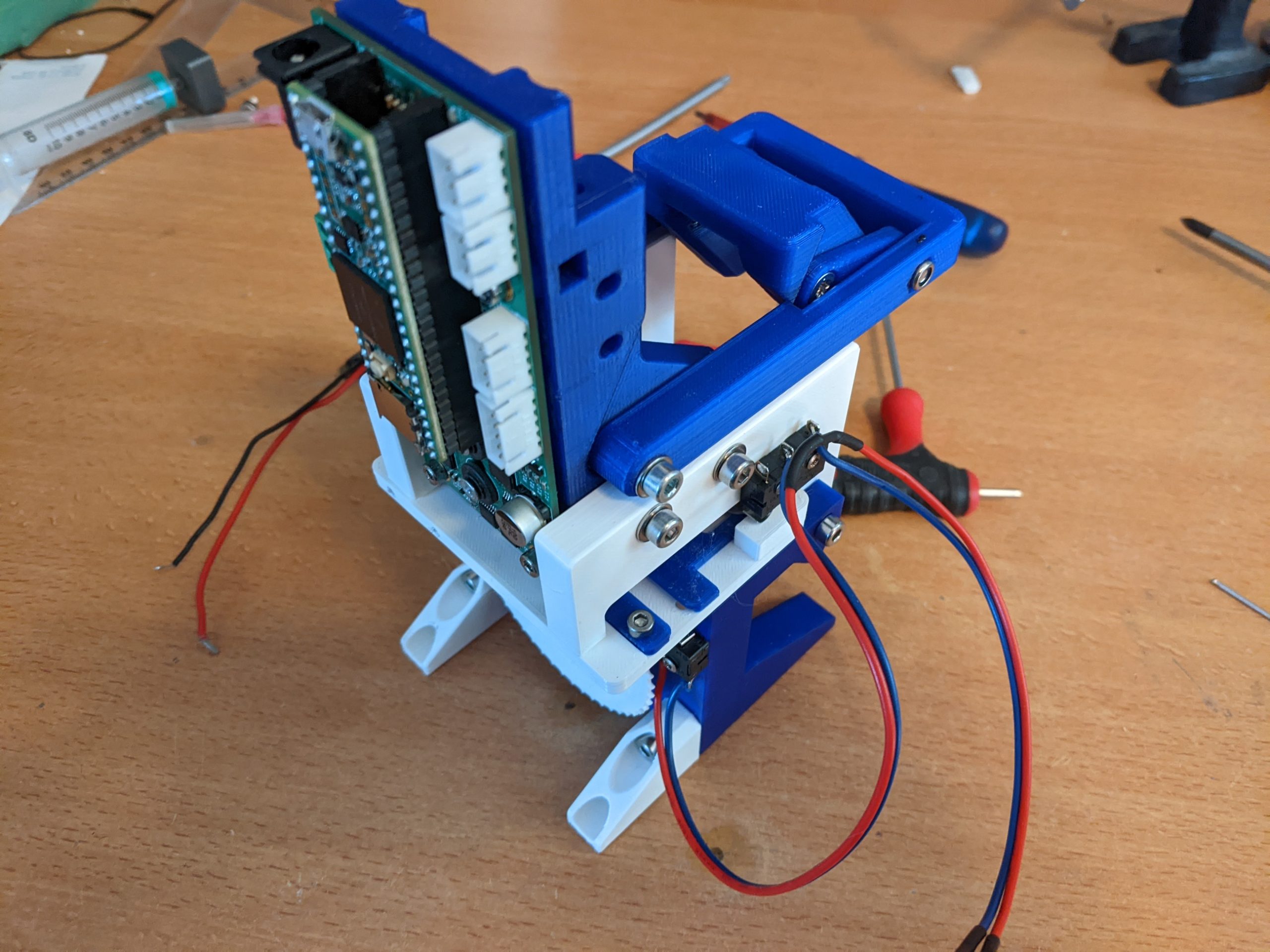
The hinges (TP-P17-00) can be mounted to the base using 2 M4 screws (DIN912 M4x25) as shown. The screws need to cut their own threads.
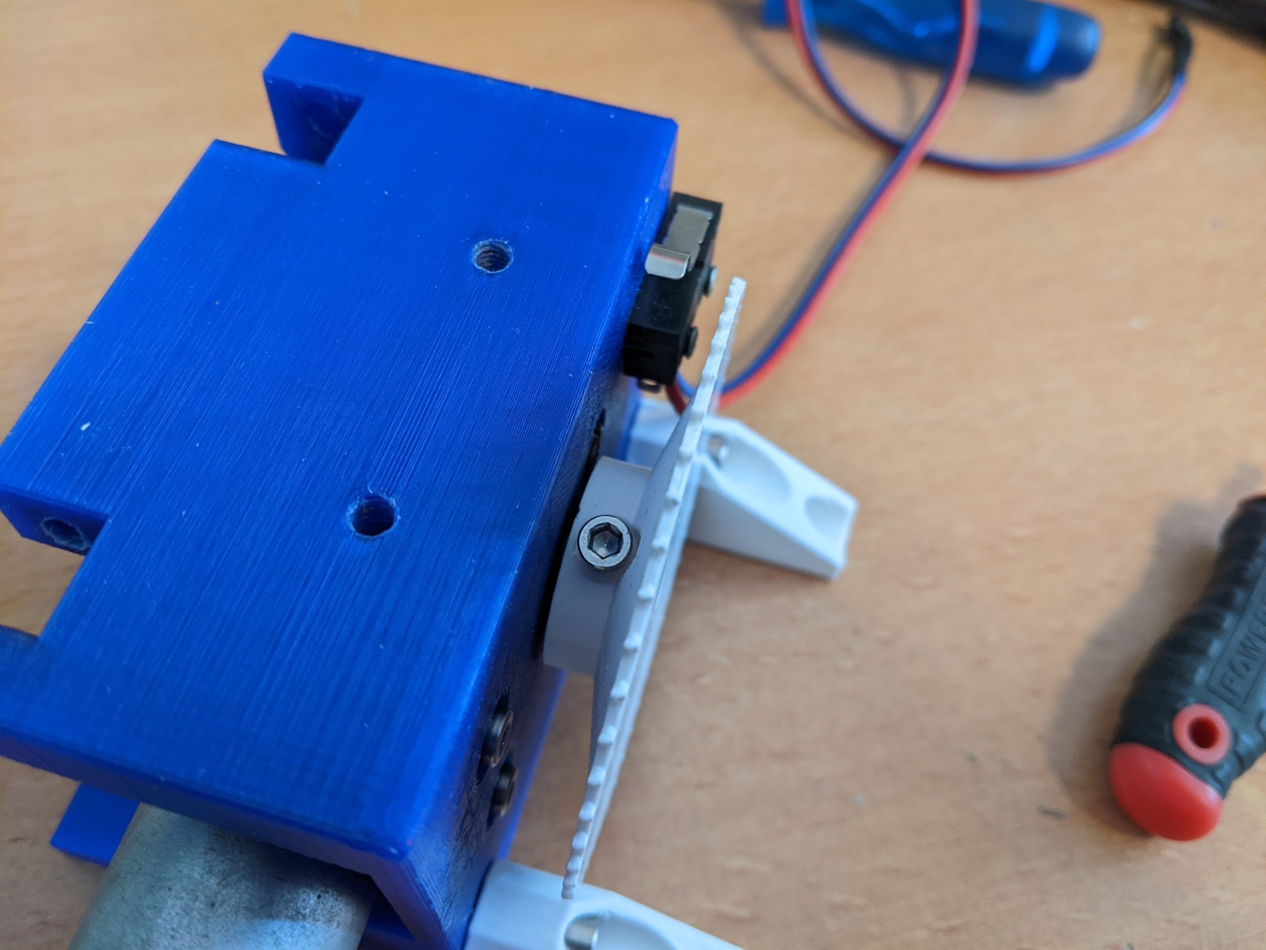
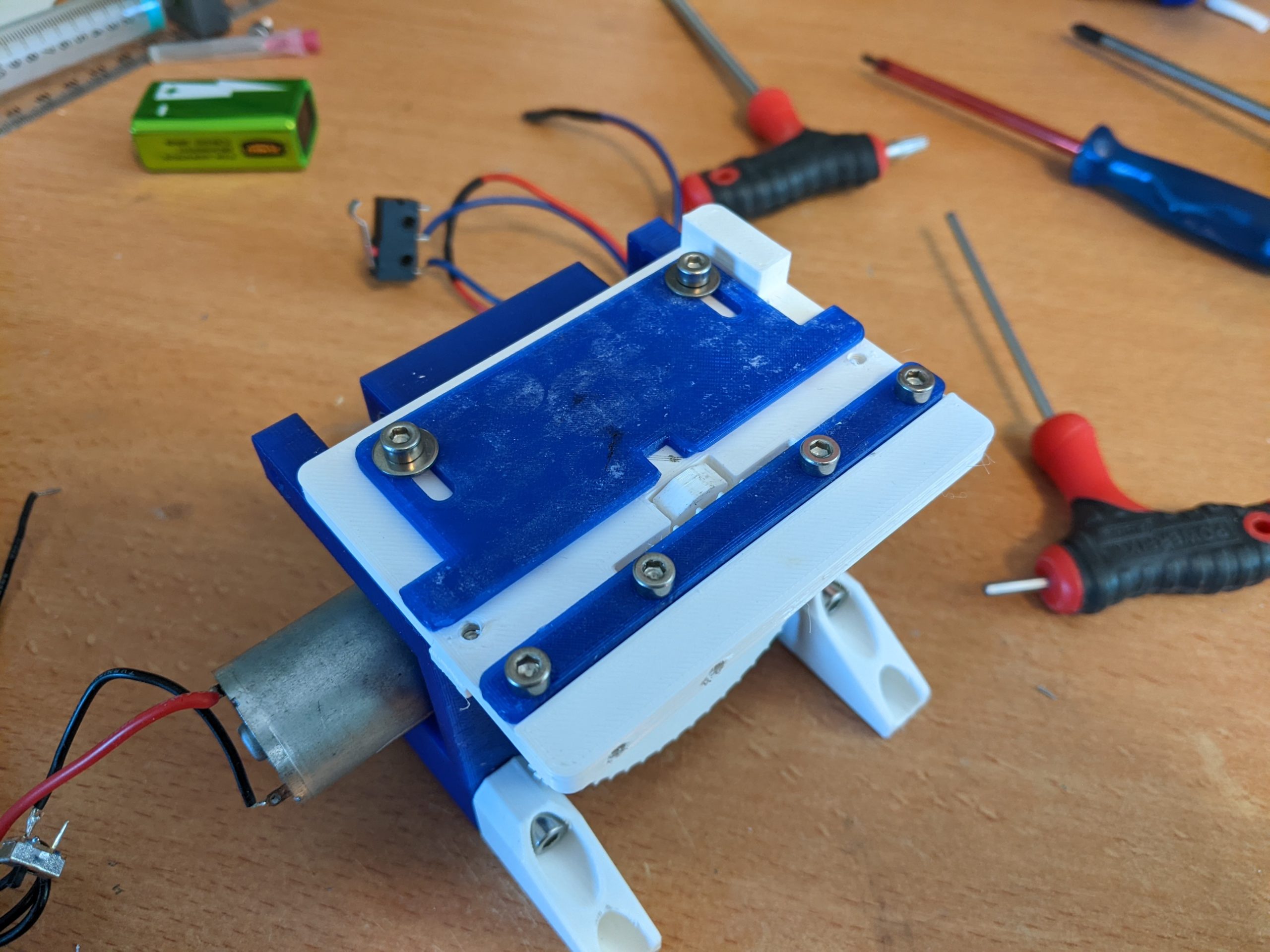
Mount the inkjet controller to the hinges using 4 M4 screws (DIN912 M4x20), 4 M4 washers (DIN1235 M4) and 4 M4 nuts (DIN985 M4). The nuts sit in the hexagonal pockets in the inkjet controller. The screws and washers fix the controller in place. Make sure both hinges are pressed down when mounting the controller.
The microswitch (5e4t85) is mounted to the hinge above the protrusion in the top plate with 2 universal screws (2.0x16mm).
The switching point can be adjusted by bending the metal part of the microswitch. The exact switching point is not important, only that the switch has triggered then the printhead is down.


Wiring diagram
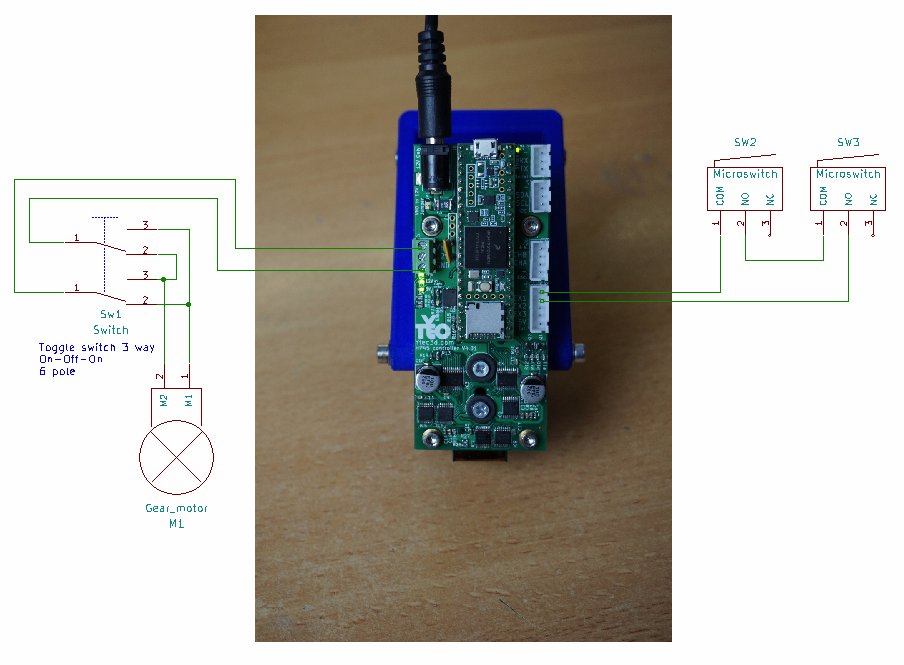
For this example the DC input connector on the top of the controller will be used. This is a 5.5mm 2.1mm pin DC jack connector. The required voltage is 12V, with at least 3A available.
The motor is easiest to wire to the screw terminal on the left side of the controller. This is directly connected to the 12V input power. “GND” and “12V” are used for this. Technically the motor does not need a switch, but it is wise to add one to turn the motor on and off, and optionally to add direction control to the motor. In the schematic the option for direction control is given, with a 3 way on-off-on toggle switch (DPDT On-Off-On).
The trigger switch is 2 micro-switches, wired in series. The switches are wired both with the NO port, between “-” and “EX1”. Only if both switches are triggered will the pulled up pin be pulled to ground.