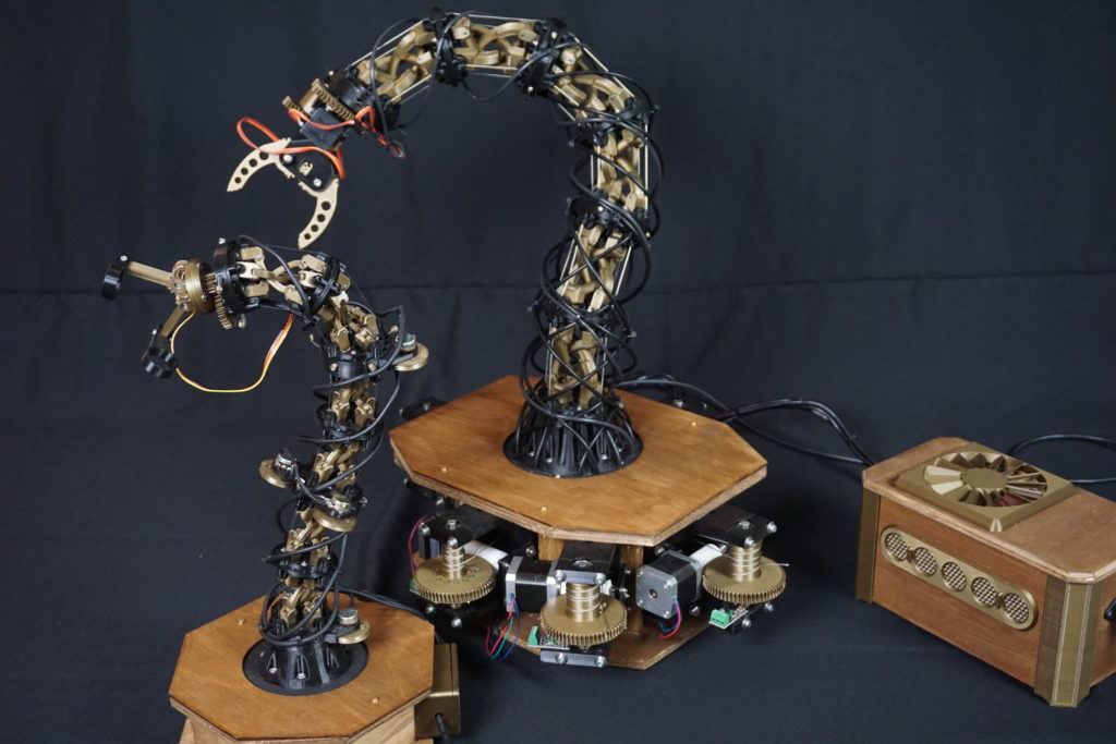
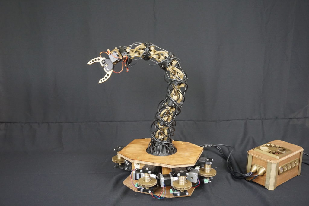
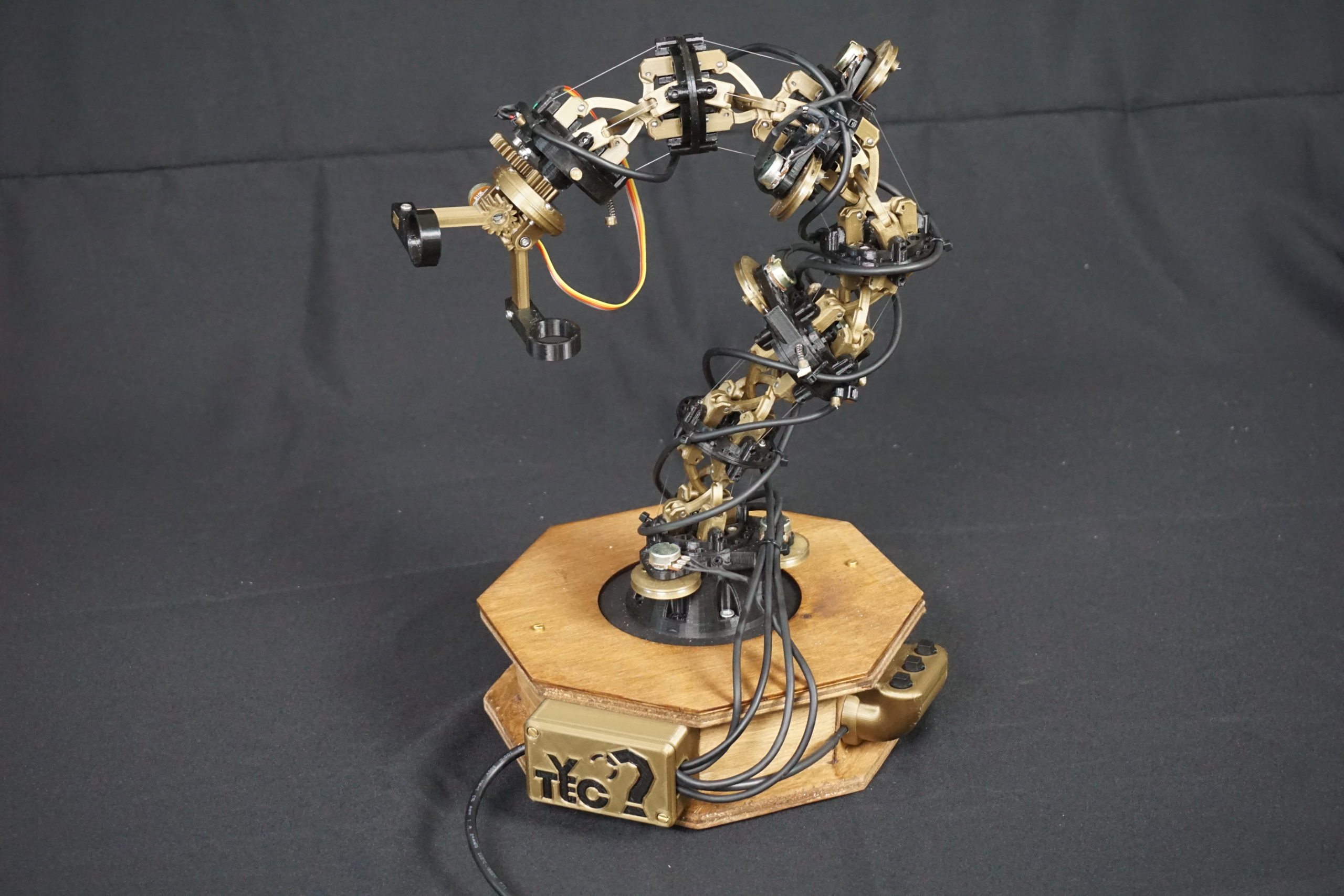
A springless animatronic tentacle mechanism that can move in all directions and is strong enough to pick things up.
Why
because I can. When has a lack of good reasons ever stopped anyone.
Also, the original spark for this project was this hackaday article. In this article the construction of a cable driven animatronic tentacle mechanism was described. While this construction used has been known for decades, and the article gave a great example, I was captivated by an idea.
Most cable driven tentacles use springs. These springs make sure that the cable tension evenly distributes itself over the length of each joint. This is a simple solution, but it presents a problem. If you want to carry 1kg, your spring needs to support this. Any load you apply will interfere with the spring distributing the load. The more weight you want to carry, the stiffer the spring needs to be. The winches are fighting these springs, so this becomes inefficient quickly. These mechanisms are only ever used to make something move tentacle like. Also, keeping the tentacle torsionally rigid is a great challenge. The tentacle in the article only moves it’s own weight, and it tends to flop over when oriented poorly. It is not load carrying. A common material used for the core of a tentacle mechanism is a speedometer cable. This cable is flexible and torsionally (fairly) rigid, but only until a certain point.
Trying to kill two birds with one stone, I wondered if it would be possible for a mechanism to distribute a force without the spring. Can you make a tentacle curve evenly without a spring, thus not being influence by any external load. Any mechanism was bound to also be torsionally rigid. This question led me down a 2 week rabbit hole of mechanisms, ultimately leading to this tentacles design.
Specs
- Length of tentacle: 60cm
- Maximum load: 0.5kg (with difficulty)
- 3 sections with in total 6 Degrees of freedom in the tentacle
- Total range of motion: 270 degrees in each direction
- 6x Nema17 stepper motors for the movement
- 2x Corona DS339HV servo in the head
- Power usage: 120W
- Teensy 3.5 in the controller
- Arduino Nano in the remote
How it works
The tentacle consists of 3 sections each being able to bend in 2 directions. Each section has 4 cables. When 1 cable contracts, and the opposite cable expands, the section bends evenly. In the base are 6 winches that contract and expand each set of cables. Bicycle gear outer cable is used to bring the cable from the winch to the joints.
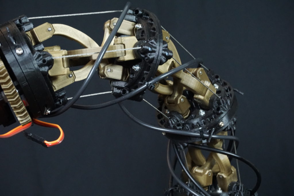
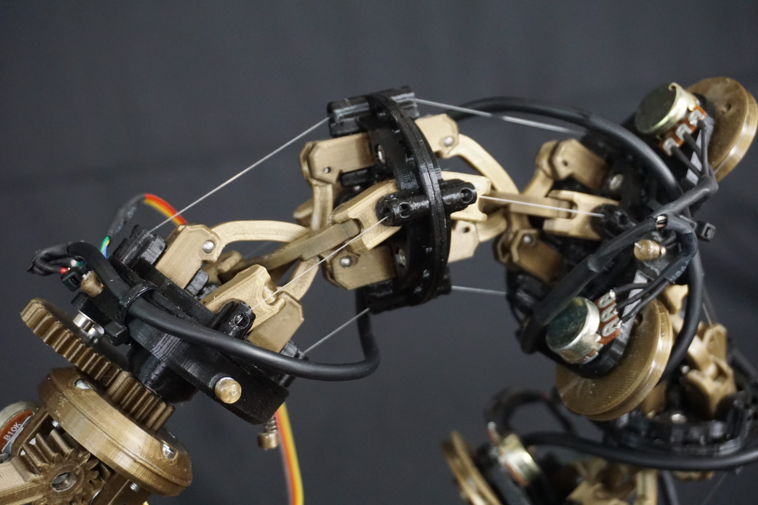
The mechanism in each section is a gear linked virtual rolling joint contact based on the motion of an anti-parallelogram. This mechanism is explained in more detail further down on this page.
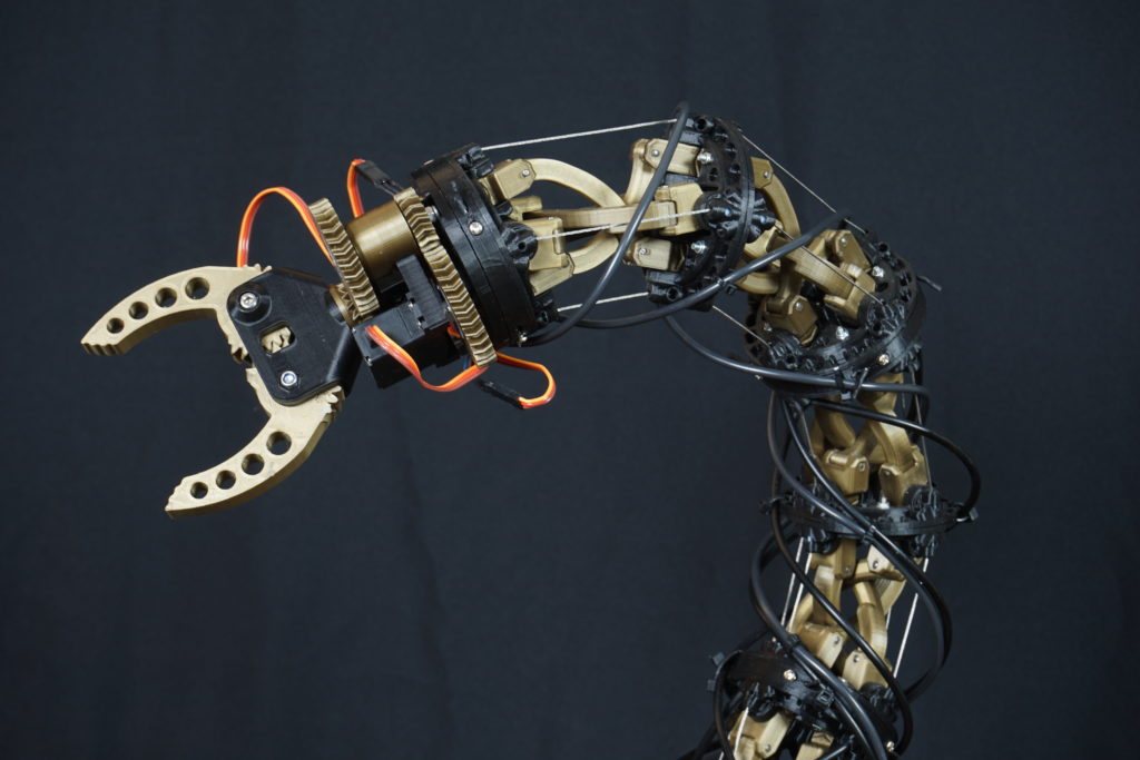
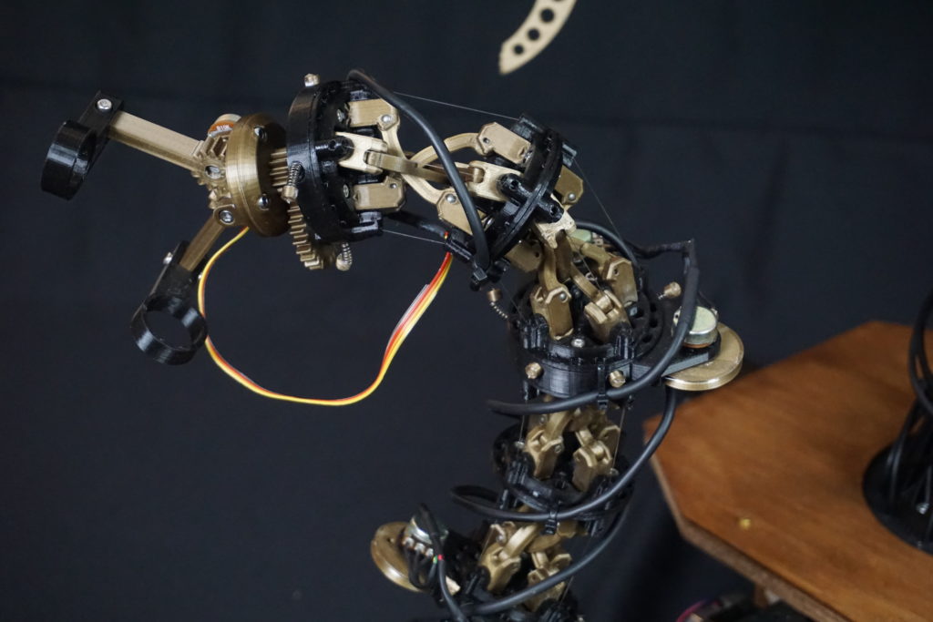
The head uses 2 hobby servos, one to rotate and one to open and close the gripper.
Controller
Controlling a machine like this is difficult. You can move the motors around one by one, but controlling it organically is a challenge. The controller is a scale version of the actual mechanism of the tentacle. The tentacle mimics the motions made by the controller, allowing for easy control.


Design process
The design and construction of this project took many turns. I will try to give a good overview, but I did not do a great job documenting this project along the way, so pictures may be a bit lacking.
Basic concept
The project started with a basic design concept. How can you make a cable driven trunk or tentacle shape curves evenly when the cables pull it one way. Springs are simple but have serious drawbacks. It seemed very possible to design some mechanical system, though in practice it turned out to be a bit more complex. I will try my best to explain, but a lot of this is a bit touchy-feely.
First a term I will use. The ability of a number several elements to always curve evenly is what I mean when I say that a mechanism is synchronized. See below an example with lines.
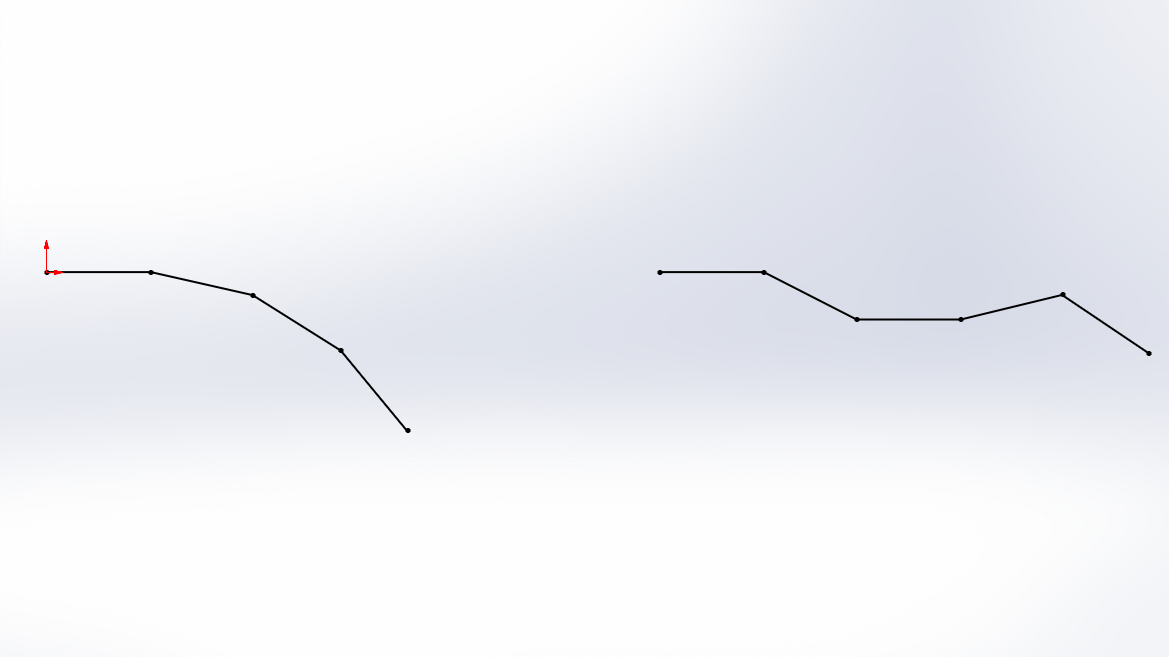
The first false start with a design involving a revolved gear in a gimballing joint. The exact design is a bit hard to explain, partially because it is a spherical gear and partially because it does not work. I had hoped that the central gear would keep any chain of elements synchronized. This failed spectacularly since the inner gears would just rotate however they wanted.
Going back to basics, I tried to design a mechanism that worked in 2D. If it would work in 2D, I could attempt to make it in 3D. The first is a series of gears linked with arms. It did actually work in 2D. However, the given design already used all 3 dimensions. I can not make this move in 2 directions.

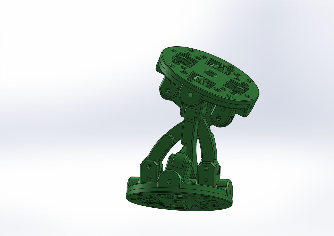
A breakthrough came with the discovery of the anti-parallelogram. The shape itself has quite a nice curve to it. If you make the place where the arms meet gears, each module of anti-parallelograms will drive the next, synchronizing the system. More importantly. This shape can be made in 3D.
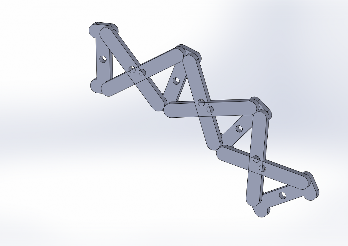
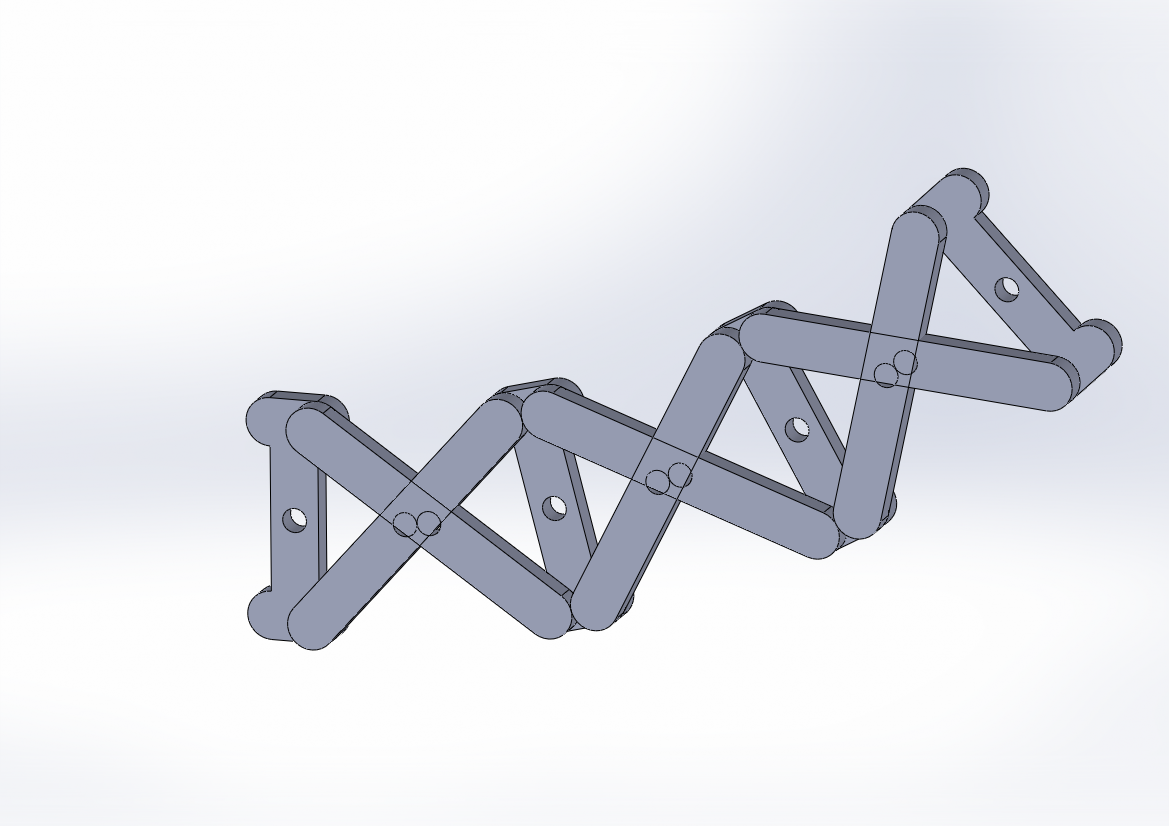
A primer on anti-parallelograms. They are a parallelogram where one set of arms are crossed, giving it an hourglass shape. The anti part comes from the fact that the non-crossed arms will turn in opposite directions. More importantly to us, the shape approximates 2 circles rolling over each other (hence the virtual rolling contact part later). Important is the center of these circles. They are behind the hinges of the anti-parallelogram. This center of the circle is where I need to mount an extra hinge to compensate for the movement of the second anti-parallelogram in my 3D joint. Another important word here is ‘approximates’. The design approximates a rolling joint, but only to a point. The furthest I have seen this shape go without horrible offsets between the 2 circles is around 90 degrees. For my design, I went with 45 degrees, which can still be made on a 3D printer.
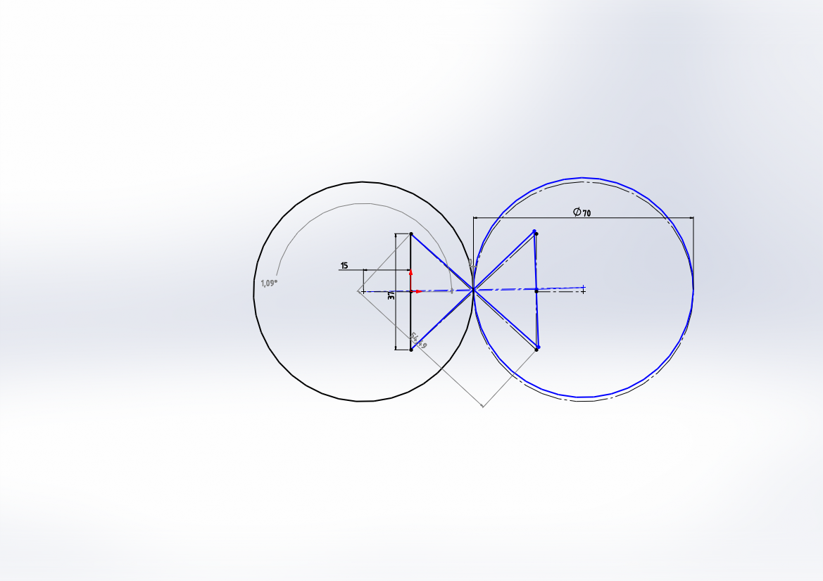
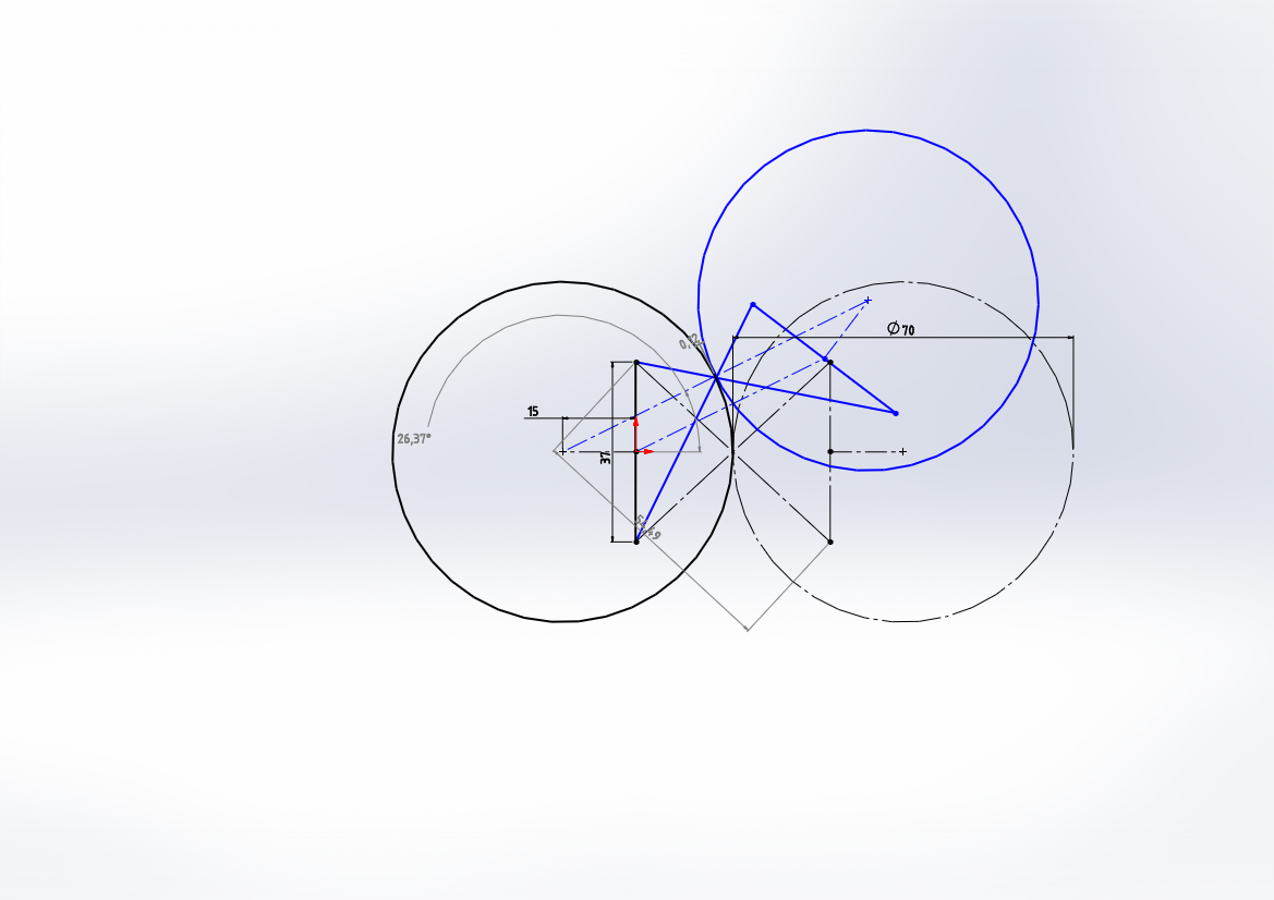
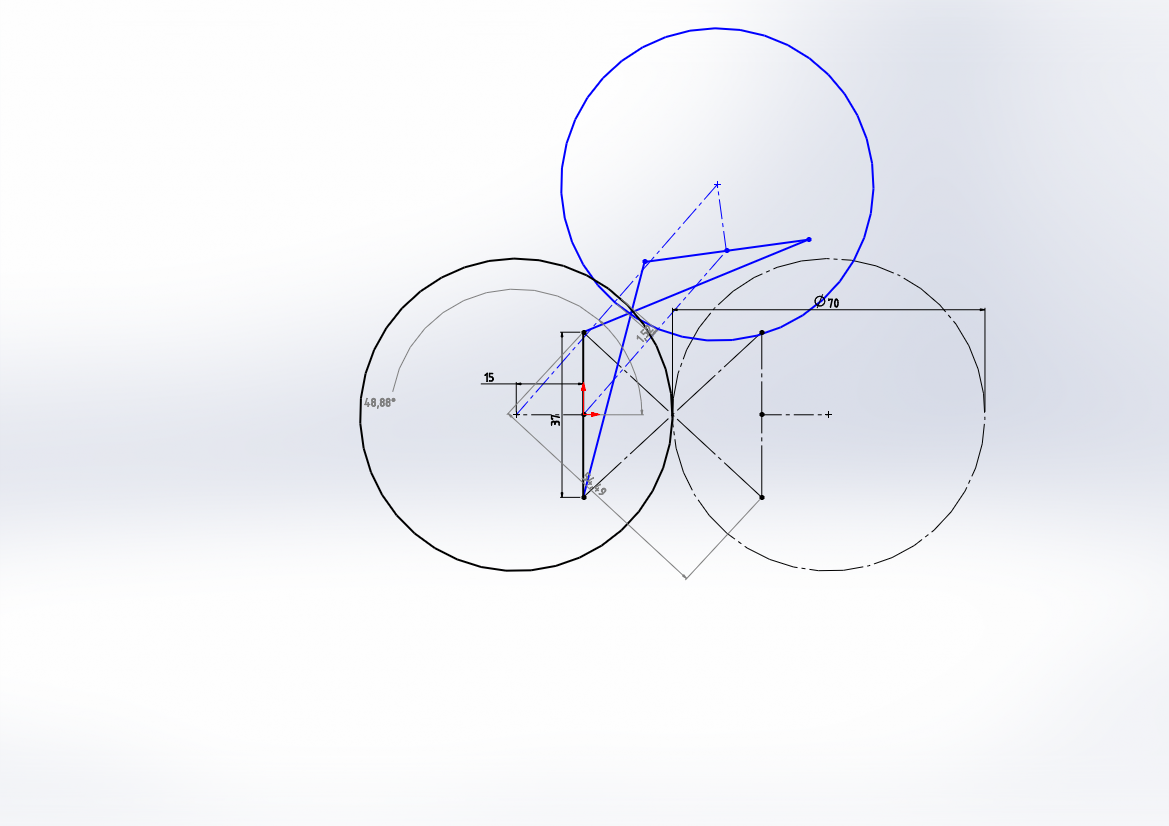
First the unlinked version of the 2D anti-parallelogram. In the concept below the arms still cross each other. In reality I could offset the arms and make it work. Now the last task was to somehow use gears to link each module together.
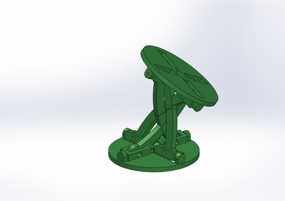
Finally, gears were added to each end. These gears attach to the next joint, transmitting it’s position. Also the parallelogram arms were altered so they no longer crossed. Holes were also added for the screws and for the cables that will drive this mechanism.
An important thing to note. The gears on these joints are tiny and cannot bear the load of the whole tentacle. Luckily the cable carriers most of the load together with compressing the tentacle itself. The gears only carry the forces required to synchronize the tentacle. While these forces increase with the load, for smaller loads this is still manageable.
I did design this mechanism from scratch. However, it did exist before in some form. I only did not know it’s name. The terms anti-parallelogram and virtual rolling contact joint became apparent in this video of Will Cogley making a bio-mimicry hand. As it turns out, the wrist is a rolling joint, and scientists have tried making mechanisms that mimic the motion. If you do not know the names used, it is a challenge to find anything.
prototype
With the mechanism sorted, I wanted to make a working prototype. Since the mechanism should be able to scale quite well, I went with 4 links. I quickly designed and made 2 winches to drive it, and added a joystick and an Arduino to control it. It was a bit of a rush job because I wanted to take it to Hackerhotel 2020, back when large groups of people together was still allowed. I was so rushed in fact, that I never took any photo’s and videos and I had to resort to asking other people present for theirs (Thanks Jenny).
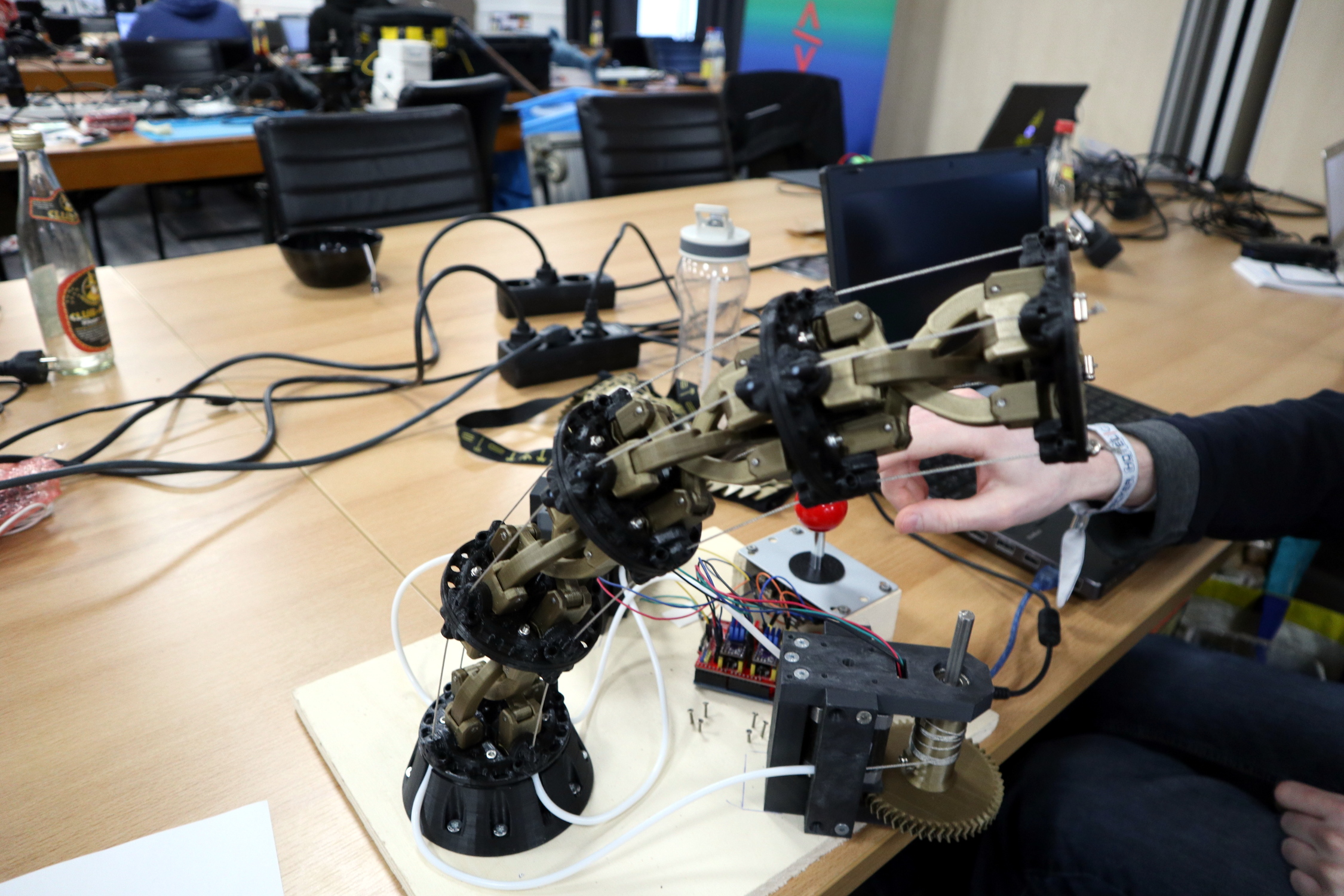
At Hackerhotel 2 things happened. First is that I discovered a flaw in this design. With 2 links the arm was very rigid, but somehow at 4 links the arm was quite flexible. After some investigation I discovered that only the middle joint is resisting any forces. The 2 outer joints do not. This discovery was quite a bummer, since one of the ideas was that you could make a whole chain of joints work this way. What I learned is that after 2 links, the strength of the sections quickly fades.
Making this and showing this of also made me realize that this thing is awesome. It may not be strong if I make it very long, but realistically, I could make a neat robot arm out of this. This led me to a 6 month project to turn quick prototype into a kind of functional robot tentacle.
Making the final tentacle
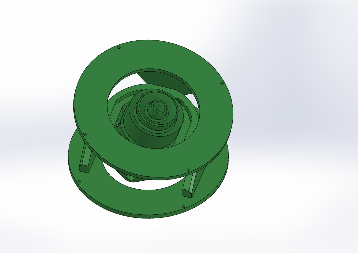
The first thing to design were new winches. The ones I had were quick, but not strong enough. I’d recon that if I ran the motors at full speed, I should be able to move the joint a full 180 degrees is around 4 seconds (hold that thought).
The first attempt was to make a winch based on a linear track. A motor attached to a screw was thought to have enough torque and speed to function. In practice this proved a bit slow, bulky, and difficult to make. Even with extra gears the winch was too problematic.
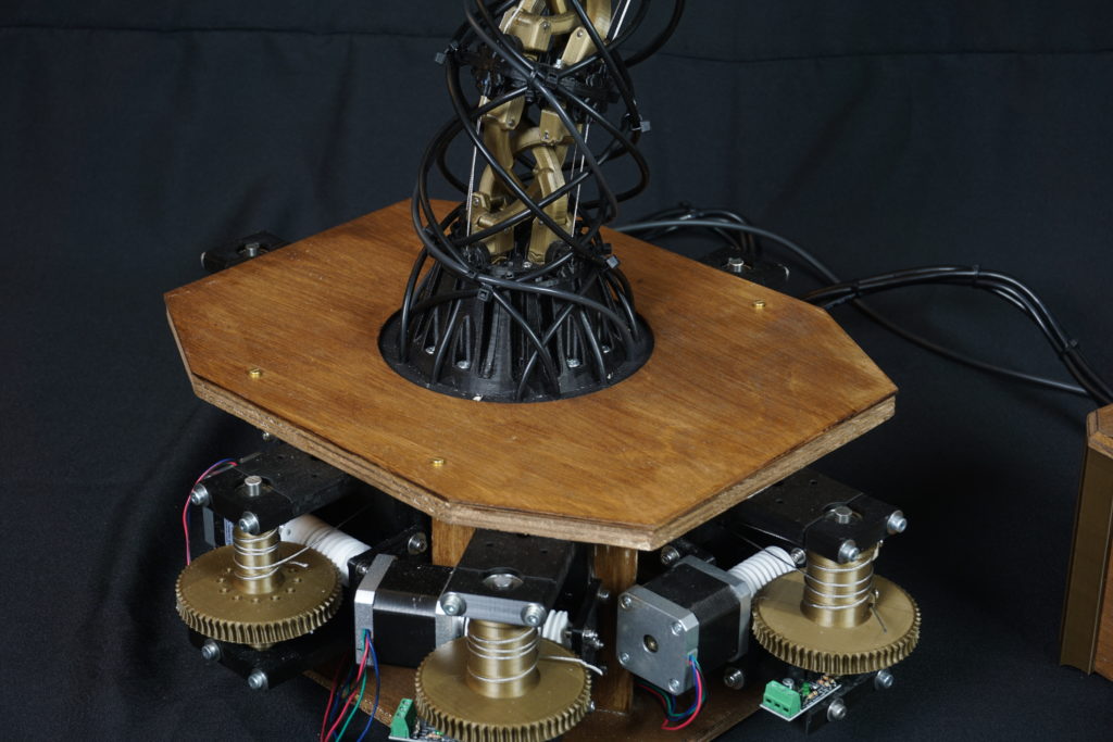
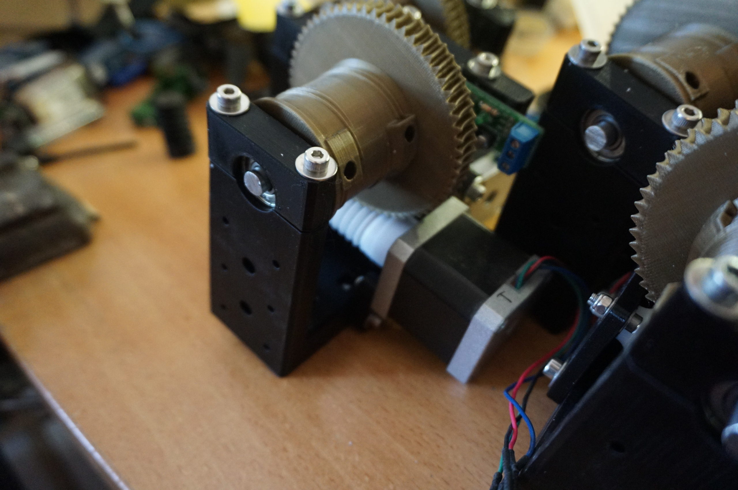
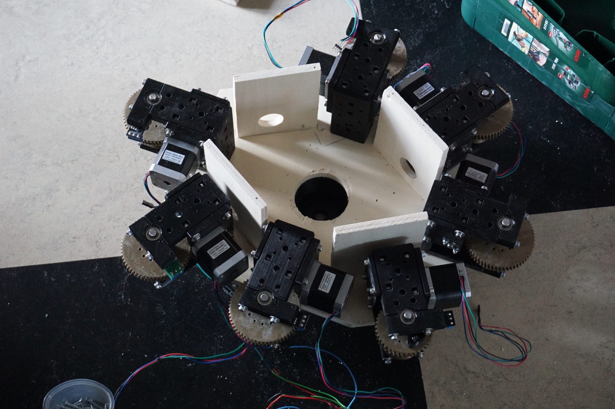
Back to the drawing board. The winches were redesigned with worm gears. This allowed me huge gear reductions in a small size. The new worms were printed in Igus I150, a bearing material. The worm gears are basic PLA. A Nema 17 stepper motor drives the worm. Each steel cable makes several revolutions around the winch before being clamped in place with a screw.
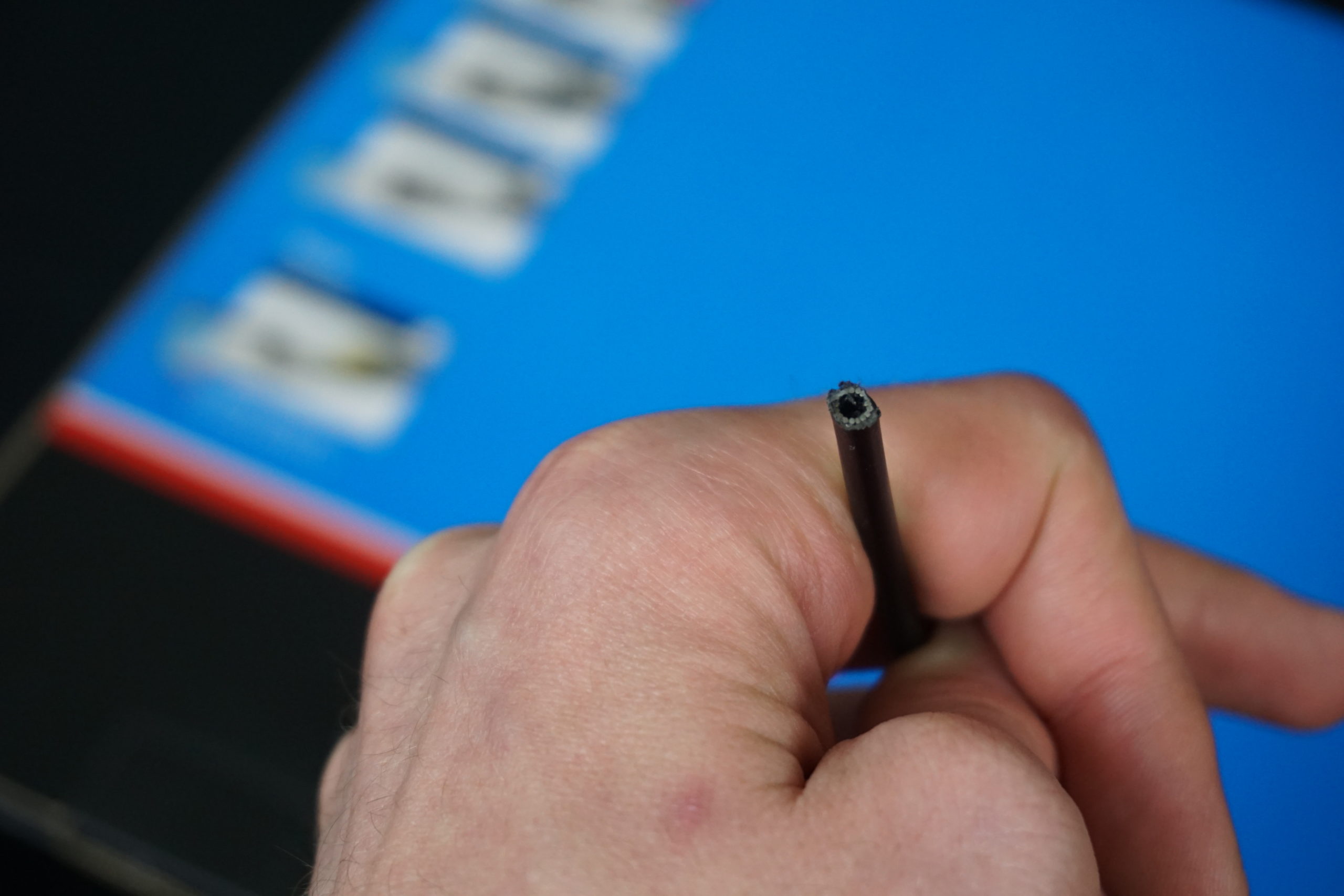
The prototype used teflon tube to get the steel cable from winch to joint. This works, but teflon tube is quite expensive. I ultimately settled on bicycle gear outer cable. It is a hollow tube with a steel sleeve and a teflon liner. It is a bit stiff, but it can handle tremendous compression forces and is relatively cheap.
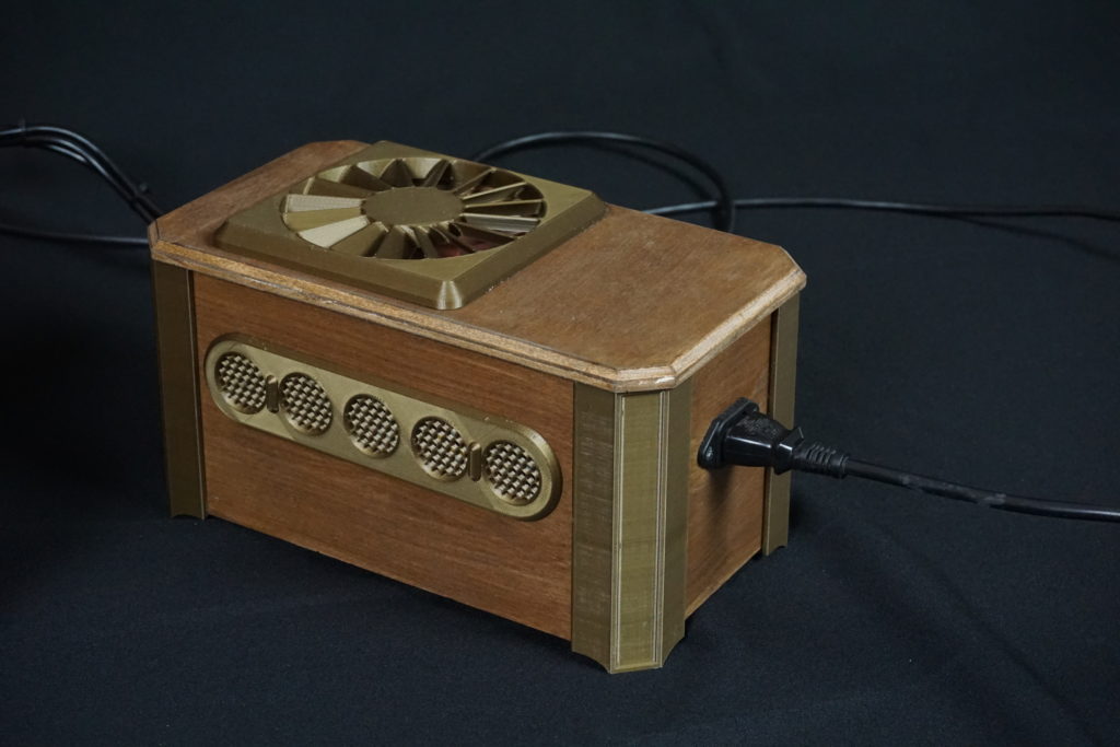
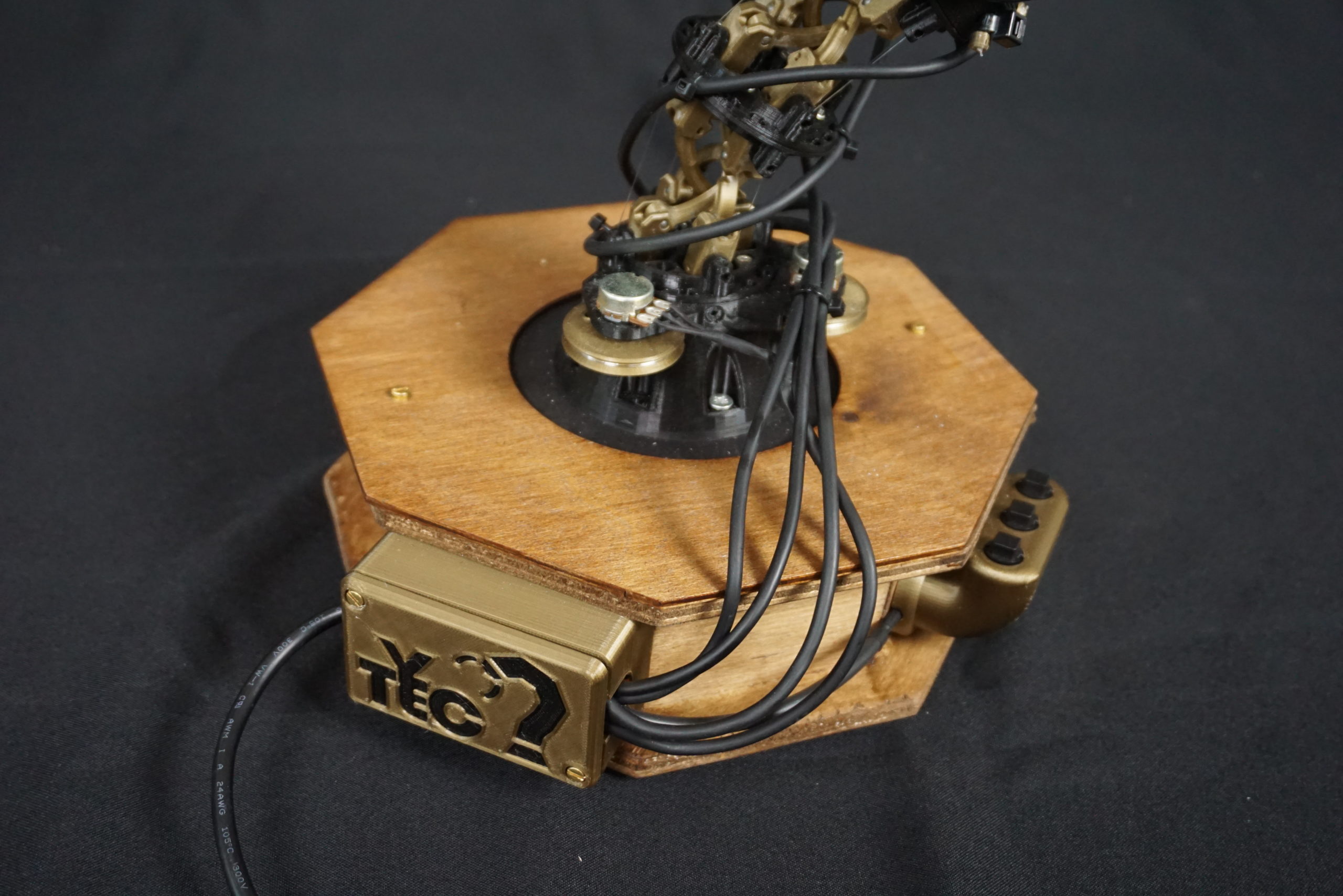
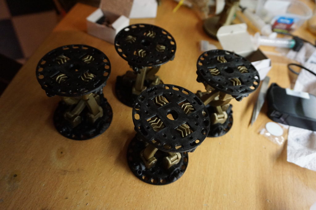
The base holds all winches, the tentacle itself, and the mess of guide tubes that comes from the winches. It is made of wood, and painted with a dark wood stain, giving it a sort of steampunk look that I really like together with gold and black filament.


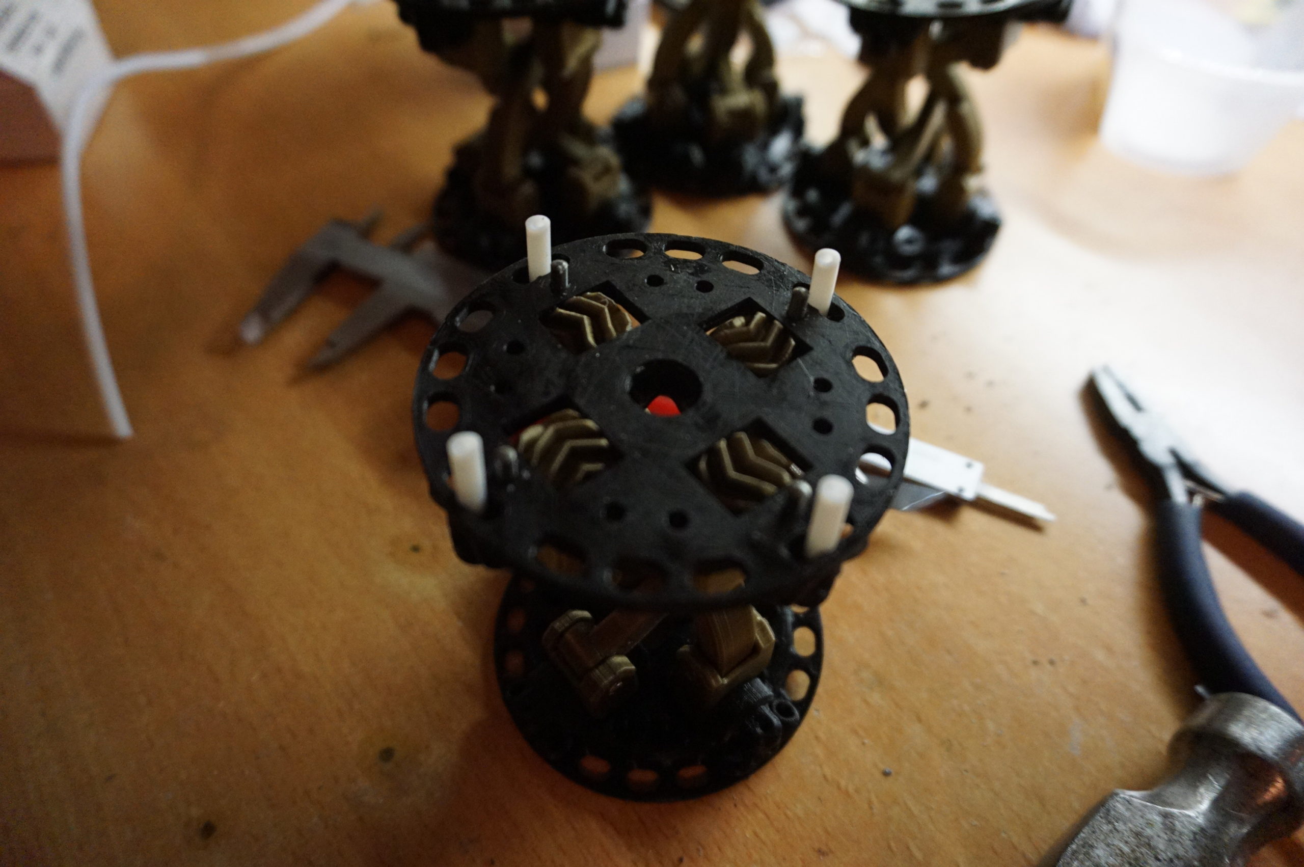
Controlling animatronics like this is usually a challenge. For most projects I built some sort of scale controller that mimics the motion. For the tentacle that left me with a new challenge. The rolling joint mechanism could only be scaled so much, and I did not feel like printing a second one just for a controller. A full week of designs went past without me finding anything simple. Getting no further, I reluctantly scaled the mechanism down as much as I could and turned it into a controller. The scale is around 60% of the full tentacle.
The controller uses the same mechanism as the main tentacle, but has some alterations. The potmeters that take the position are mounted to each section, instead of in the base. Also I used fishing line instead of the steel cable used in the main tentacle.
The base holds the controller (an Arduino Nano) that takes all the potmeter positions and transmits them to the motor controller. There are also buttons to start and stop the motion, the rotation and the gripper. The base has a concrete block poured in it to give the the mass not to move when you control the tentacle. It does not look like it, but this controller weight over 3kg.
The first gripper was designed to be cable driven. At it’s base it has 2 pulleys. One opens the gripper, the other rotates it. A worm gear ultimately opens the gripper.
This mechanism was at the very end of the tentacle, after the guide tube makes 3 full revolutions around the arm. At each revolution the cable encounters more friction. When I got to the gripper, I had no force left whatsoever. Even my strongest winches could not move the gripper. This head would not work. I had to redesign it.
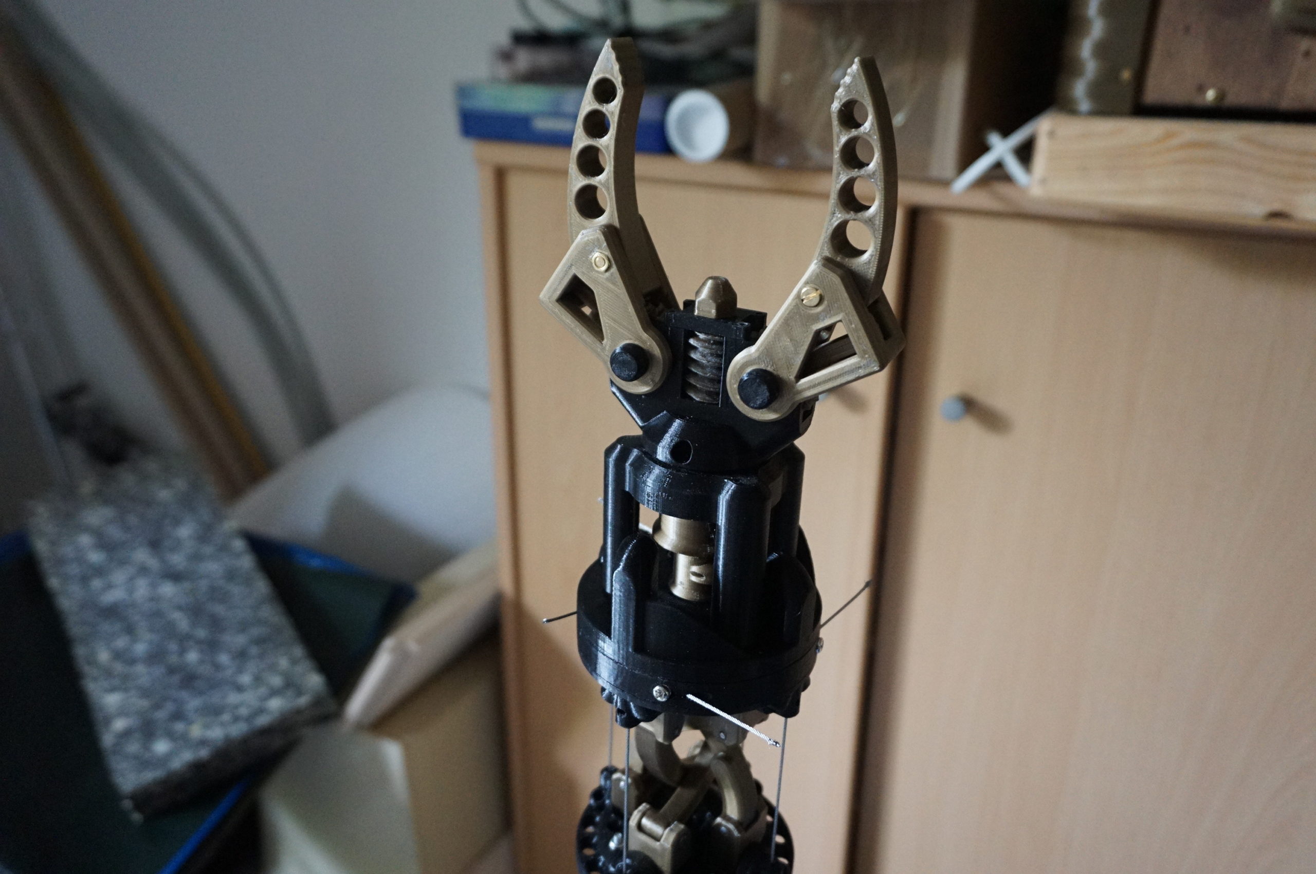
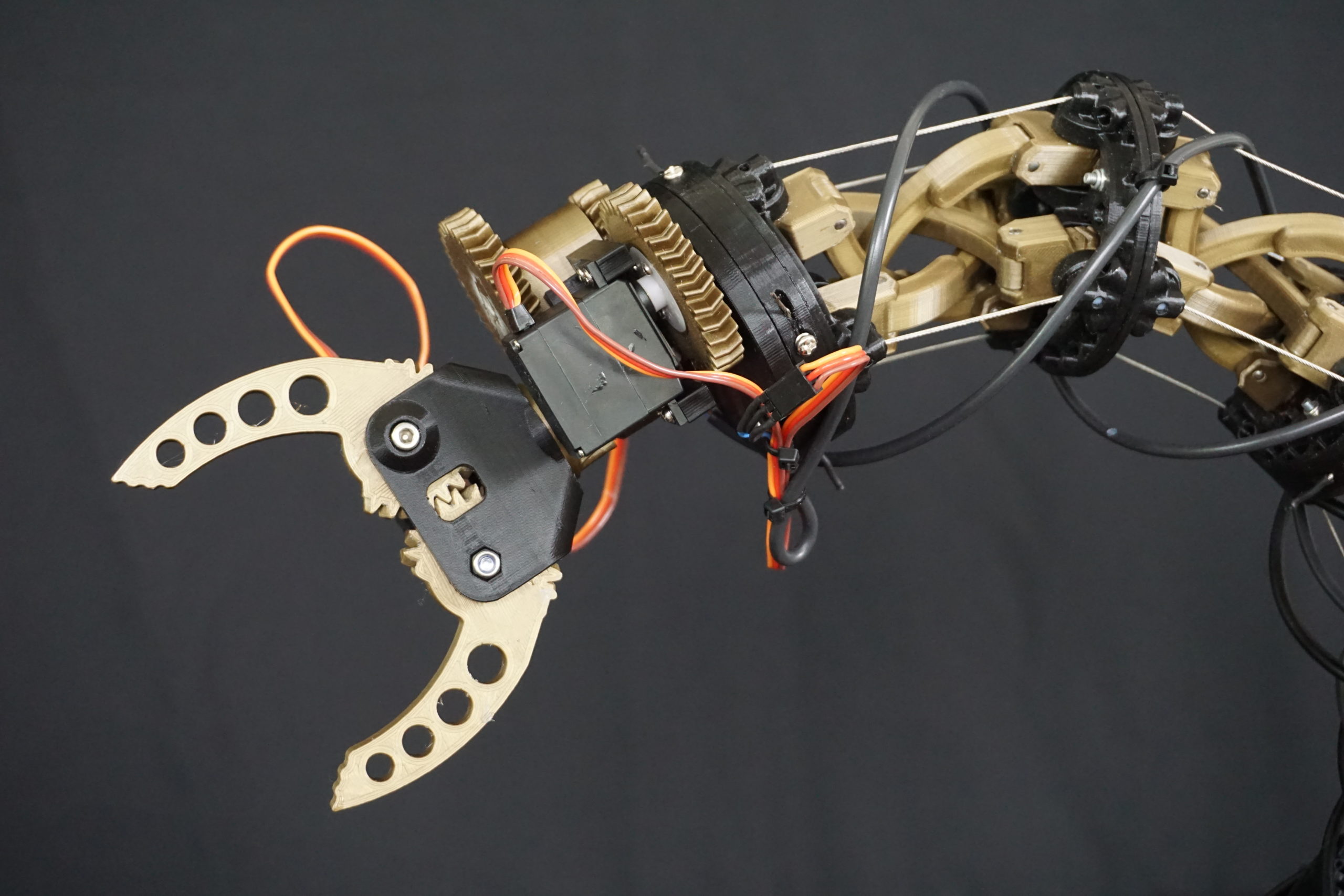
The new head uses servo motors. This is a shame since I liked the mechanical look of the cables, but it does result in a lighter head that can handle more force. The servo’s used are DS339HV with a range of 90 degrees. To get the head to rotate more than 90 degrees I added a 4:1 gearing to increase the speed and range. The gripper itself is directly mounted to the servo.
Last is the control box. Initially I wanted to fit the power supply and motor drivers in the base, but this quickly became impossible. Some idiot (me) got all sorts of guide cables in the base, leaving no space for motor drivers. I made a control box that houses the power supply, microcontroller, motor drivers and cooling fans.


Compromises made
The first compromise I had to make was with the motor drivers. I like machines that do not require hearing protection to run. Since I had 6 stepper motors attached to a wooden structure, I had to pick silent stepper drivers. Fortunately, in 2020 these exist in the form of TMC2100 drivers and they are not even that expensive. This is compensated by the fact that each driver only does 1.2A. Heavier silent drivers exist, but they quickly become expensive.
To keep the tentacle actually moving I had to reduce the speed more and more. I started with a 1:30 worm reduction and a 40mm diameter winch, but ultimately had to go to a 1:60 worm reduction and a 20-30mm winch diameter. I am really saddened to be forced to make it this slow, but it is the best I can do with the current design.
The second compromise is the head. As mentioned the gripper used to be cable driven, just like the tentacle. However, the curvature in the guide tube meant that I lost more and more force the further towards the head I got. I tried to make the rotation and gripper work with the cable, but simply could not create enough force. The servo’s are aesthetically a bit less pleasing, but are a lot more functional.
Improvements left
More power. While the basic design for the winches has not changed, the gear ratio for the heaviest joints has been increased 4x just to get the damn tentacle to move reliably. The original end to end time was designed around 4 seconds, but I now do around 15. Even now, some joints (especially the furthest ones) occasionally skip. Using Nema 23 with heavier drives, closed loop steppers or even full servo’s might be better for this project. This is such a huge overhaul that if I ever will do it, it will be for a completely new build.
Less flex in the cable guide tubes. The current tubes can handle the stress of the steel cables, but I have found that every degree you bend takes force away from the mechanism. This problem worsens with the square of the angle. The tube spirals around the tentacle, so each joint gives a free 360 degrees flex without any other angle. This got so bad that at the old cable driven gripper I had no force left. In any next design I would strongly minimize the angle made by the tube.
I have also seen mechanisms that can help me with this. In this youtube link you can see a virtual rolling joint that does a full 90 degrees each way. I can either have the gear link with another module and have a full 180 degrees in a single section, or simply skip the gears and have the same reach I have right now for each section. Another great thing is that this mechanism has a hollow core. This would allow guide tubes to pass through the center. This prevents me from having to spiral them around the outside, which is most of the current bending in the guide tube. The only drawback is that this design is difficult to 3D print, though I see that more as a challenge than an insurmountable problem.
CAD files and firmware
Shared without any guarantee or instructions. The tentacle project was not documented as a build guide. I share the files for the enthusiast who wants to give it a go, but has technical skill to figure stuff out themselves, or someone looking for reference.

Joint assembly
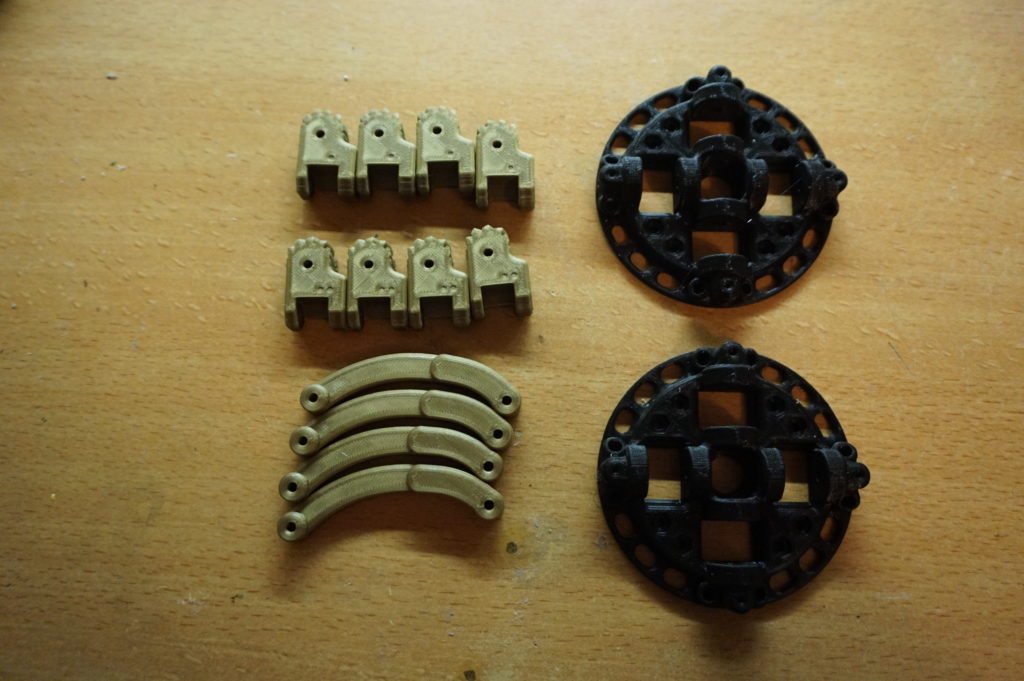
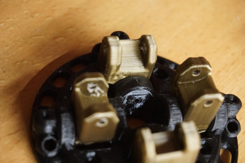
To give anyone attempting to make a joint some help I do have some photo’s of me assembling a single joint. The files are in the download above, under STL files -> Tentacle mechanism. In a tentacle joint are:
- 2x end pieces (ATM-10G-P01-00)
- 4x hinge blocks with 1 dot (ATM-10G-P03-00)
- 4x hinge block with 2 dots (ATM-10G-P04-00)
- 4x curved arm (ATM-10G-P02-01)
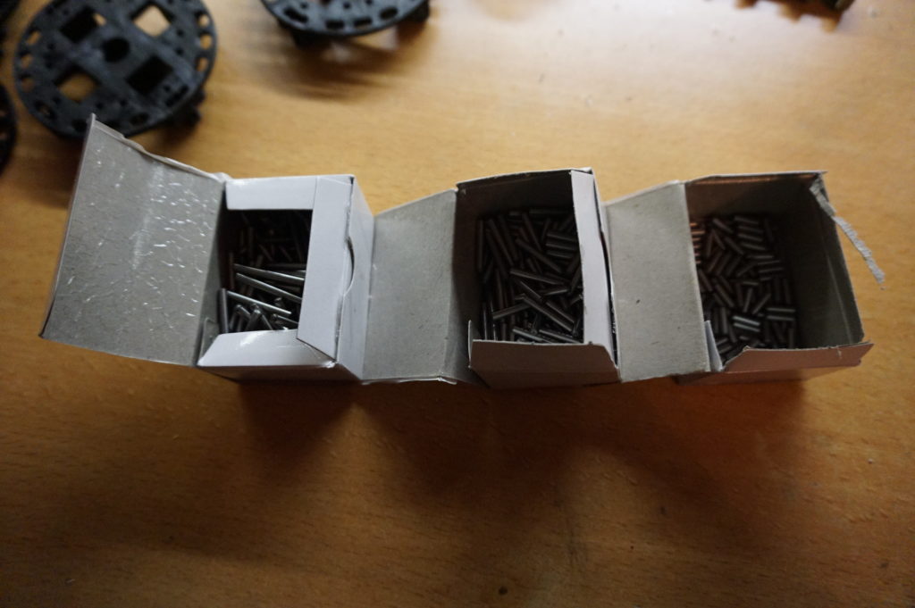
- 8x 3x20mm pins (I used DIN6325 H7 hardened dowel pins)
- 8x 3x28mm pins (I used DIN6325 H7 hardened dowel pins)
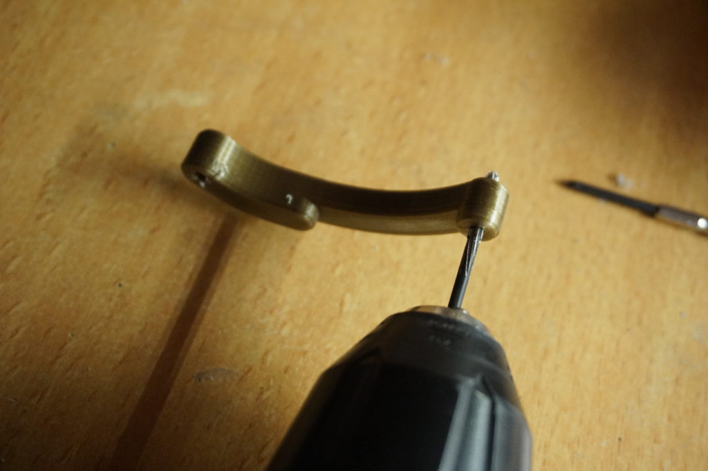
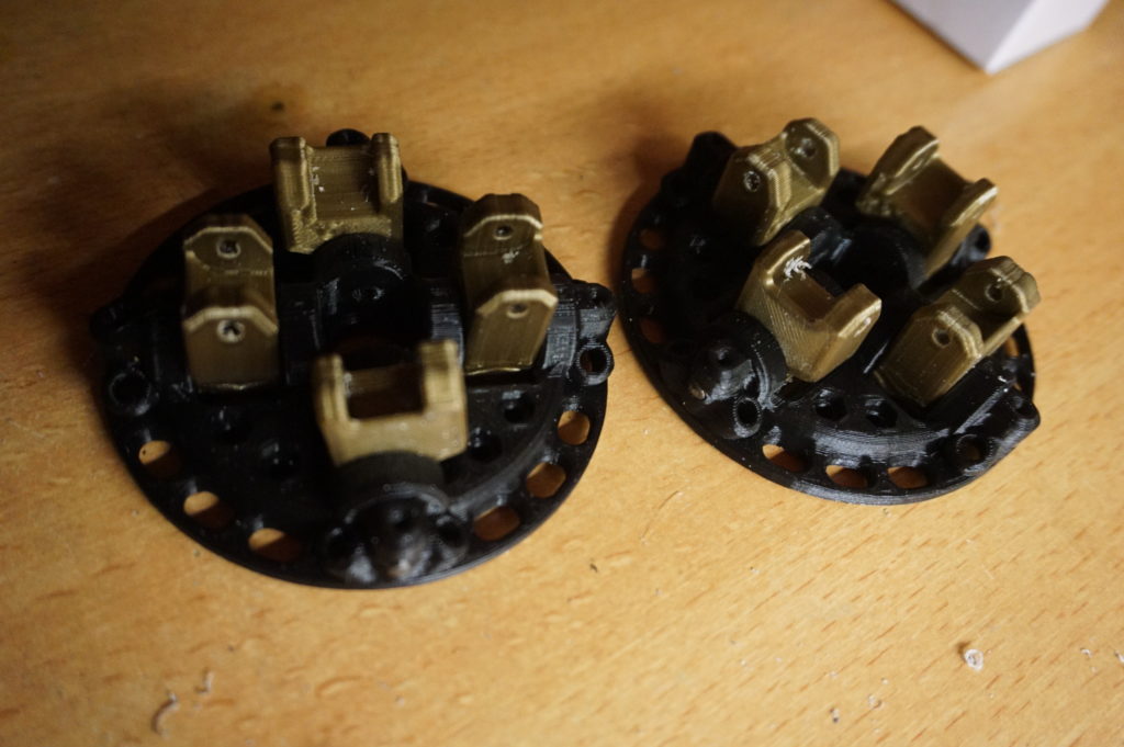
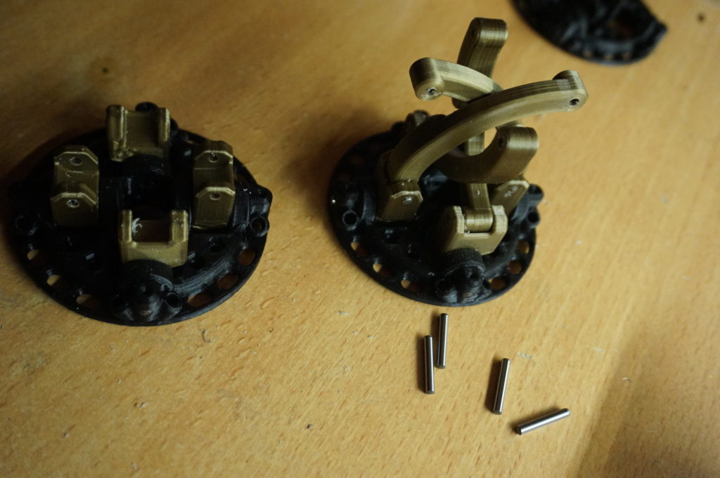
Before use, all parts were reamed using either a 3mm drill, or if you have it, a 3mm H7 reamer. Each end piece needs 4 hinge blocks mounted with the 3x28mm pins. One end piece gets all the hinges with 1 dot, the other the hinges with 2 dots. The dots face to the inside. The curved arms are mounted with the 3x20mm pins as shown and need the cutouts facing each other. Not reaming the holes properly will make the mechanism run with a lot of resistance. If you have already assembled a joint, moving it around a lot will loosen it a bit. The mechanism will get a bit more loose over time.
When making multiple joints, make sure all joints are mounted the same way around. 3x10mm pins can be used to index the joints. There are holes for 4x2mm teflon tube as a bearing surface for the cable. M3 screws are used to attach each joint. Make sure the heads do not protrude past the end piece’s surface. 2 joints meet with a one dot on one side and a two dot on the other. 2x one or 2x two do not go together. The functional limit is 2 joints, though I tested up to 4 (and more should be possible). The mechanism becomes more flexible the more joints you add.
To drive the tentacle I used 1mm stainless steel cable, though any 1-1,5mm cable should work. Do bear in mind that the length of the cable does vary a few millimeters per joint when it is moving across its range of motion. This needs to be compensated for.
License

The project described on this page is licensed under the Creative commons – Attribution – ShareAlike license.
Looks awesome 😀
Have you considered merging it with GLaDOS lamp?
Thanks for the great write up and guide. Stumbled onto this while researching some tips for building my own controlled tentacle. I’m very much a tinkerer, new to the animatronic world, and not a programmer, so like to stick to manual control mechanisms (though aren’t afraid of using lots of custom-cut gears). Def want to continue with interactive mechanical art, though, so thanks again for the inspo.
The aesthetic of your tentacle also reminded me of a “time machine” lamp of mine with the polished timber and and brass.
I don’t have any pics of the fledgling tentacle yet, but a many-geared mechanism of mine is documented here: https://fischer.com.au/zen2/
(and lamp is shown here: https://fischer.com.au/patterns/ )