For the guide on assembling the mechanics, click here
For the people that want to assemble their own HP45 controller the following guide is made to help them assemble and test the board. The guide gives a step by step of what components go where. The guide can be used to either solder a board by hand or place the components and reflow. The guide is given as a tool to help assembly with no guarantee for success. The used components have small pitches and might be heat sensitive.
Required tools
To assemble an HP45 controller the following tools are required
- A temperature controlled soldering iron with a fine tip for SMT work
- Solder fume extractor
- Desoldering wick
- Flux
- Phillips PH1 screwdriver
- Isopropylalcohol for cleaning the board
Optionally a reflow oven can be used to solder the board. The exact tools and process then depend on the exact toolchain required for your reflow oven.
Bill of materials
To make a full controller the following components are required. In the remarks some specs can be mentioned if they are important to the function of the controller.
| References | Value | Qty. | Description | Package | Remarks |
| C1, C5, C7, C9, C11 | 1μF | 5 | SMD capacitor | 0603 | |
| C2, C3, C6, C13, C14, C15, C17, C18, C19 | 0.1μF | 9 | SMD capacitor | 0603 | |
| C8 | 0.1nF | 1 | SMD capacitor | 0603 | |
| C4 | 22μF | 1 | SMD elec. capacitor | Ø4mm | No taller than 10mm |
| C10, C12 | 100μF | 2 | SMD elec. capacitor | Ø8mm | |
| C16 | 1μF | 1 | SMD elec. capacitor | Ø4mm | |
| Con1 | – | 1 | HP45 connector | HP45 connector | |
| D1, D3, D4, D5, D6 | green | 5 | LED green | 0603 | |
| D2 | If 1A+, Vf 0.5V – | 1 | Schottky diode | SOD-323HE | |
| F1 | 4A, 15V+ | 1 | Polyfuse through hole | Through hole | |
| F2 | 0.5-1A, 15V+ | 1 | SMD Polyfuse | 1812 | |
| F3 | 1-1.5A, 15V+ | 1 | SMD Polyfuse | 1812 | |
| IC1 | LMR36510 | 1 | Switching power regulator | SO-PowerPAD-8 | |
| IC2 | 74HC123 | 1 | Monostable Multi-vibrator | TSSOP-16 4.4x5mm | |
| IC3, IC4 | TLC59213 | 2 | LED Lighting Driver | TSSOP-20 4.4×6.5mm | |
| IC5, IC6, IC9 | HEF4017 | 3 | Decade counter | SSOP-16 4.4×5.2mm | VDD 15V |
| IC7 | HCF4081 | 1 | And gate IC | TSSOP-14 4.4x5mm | VDD 15V |
| IC8 | LM311 | 1 | Comparator | SOIC-8 3.9×4.9mm | |
| J1 | 5A + | 1 | 3.5mm screw terminal 3x | screw terminal 3.5mm 1×3 | |
| J2, J4 | – | 2 | JST-XH connector | JST-XH 3x straight 2.5mm | |
| J5 | – | 1 | JST-XH connector | JST-XH 5x straight 2.5mm | |
| J6 | – | 1 | JST-XH connector | JST-XH 4x straight 2.5mm | |
| J8 | 5A + | 1 | DC barrel jack | DC barrel jack through hole | |
| L1 | 22μH, 1A + | 1 | Inductor SMD | Taiyo-Yuden 5040 | |
| Q1, Q2 | – | 2 | N-channel Mosfet | SOT-23 | |
| Q3 | 78-SIRA12DP-T1-GE3 | 1 | N-channel Mosfet | SO-8 PowerPAK | |
| R1, R2, R3, R5, R8, R10, R11, R12, R17, R25, R26 | 2k2Ω 1% 0.1W | 11 | Resistor | 0603 | |
| R4, R16, R19, R22, R24, R28 | 10kΩ 1% 0.1W | 6 | Resistor | 0603 | |
| R6, R7, R9, R14, R15, R18, R21, R27 | 1k2Ω 1% 0.1W | 8 | Resistor | 0603 | |
| R13, R20 | 30Ω 1% 0.5W | 2 | Resistor | 0805 | |
| R23, R29, R30 | 330Ω 1% 0.1W | 3 | Resistor | 0603 | |
| uC1 | Teensy 3.5 | 1 | Micro-controller | Teensy 3.5 | Requires 2x 24 pin 2.5mm female header |
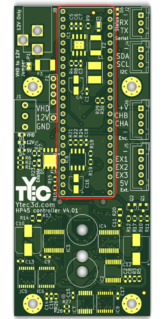
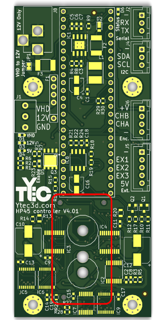
Part locations and orientation
The parts location are given roughly from small to large, to aid some forms of assembly. This order is not a hard requirement, and as long as all components are placed in the correct spot in the correct orientation, the controller will work.
For some of the smaller components like resistors and capacitors, there will be 2 components in a larger circle. On the IC’s and the large mosfet, the extra circle notifies where pin 1 is. On polarized components the – and sometimes the + is shown.
Resistors
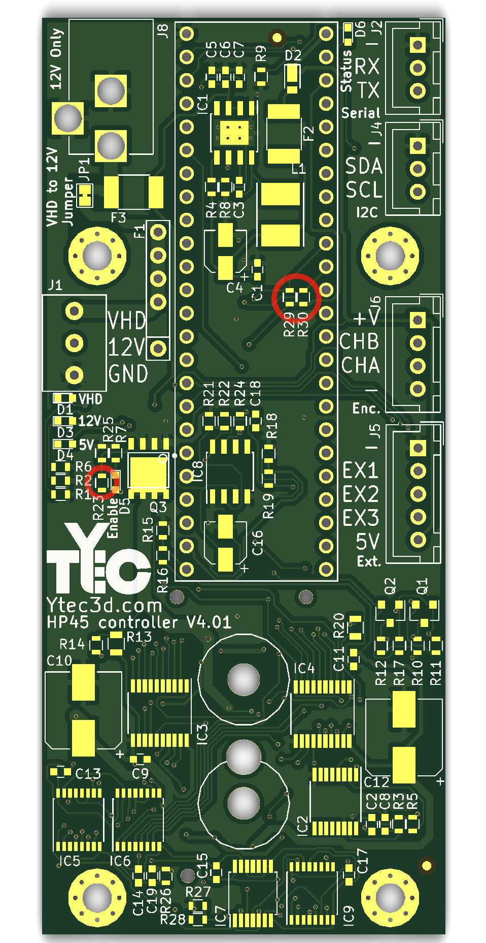
330Ω resistors
There are 3x 330Ω resistors. These are 0603 0.1W 1% accurate resistors. These resistors have no polarity.
The references for the 330Ω resistors are:
- R23
- R29
- R30
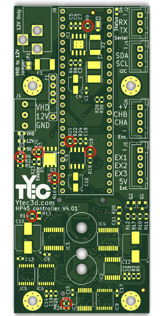
1.2kΩ resistors
There are 8x 1.2kΩ resistors. These are 0603 0.1W 1% accurate resistors. These resistors have no polarity.
The references for the 1.2kΩ resistors are:
- R6
- R7
- R9
- R14
- R15
- R18
- R21
- R27
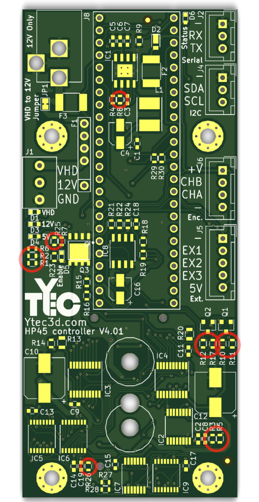
2.2kΩ resistors
There are 11x 2.2kΩ resistors. These are 0603 0.1W 1% accurate resistors. These resistors have no polarity.
The references for the 2.2kΩ resistors are:
- R1
- R2
- R3
- R5
- R8
- R10
- R11
- R12
- R17
- R25
- R26
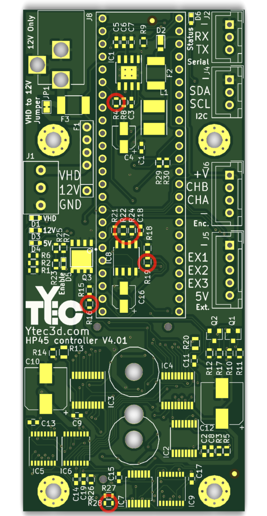
10kΩ resistors
There are 6x 10kΩ resistors. These are 0603 0.1W 1% accurate resistors. These resistors have no polarity.
The references for the 10kΩ resistors are:
- R4
- R16
- R19
- R22
- R24
- R28
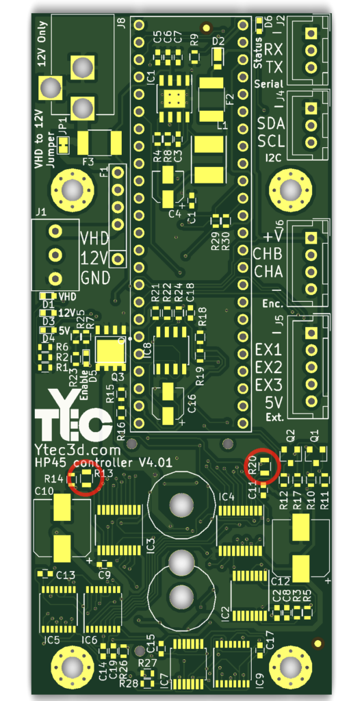
30Ω resistors
There are 2x 30Ω resistors. These are 0805 0.5W 1% accurate resistors. These resistors have no polarity.
The references for the 30Ω resistors are:
- R13
- R20
Ceramic capacitor
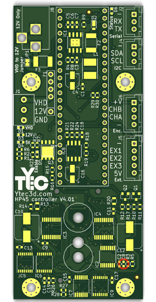
0.1nF Capacitors
There is 1x 0.1nF capacitor. this is 0603 10% 25V. The capacitor has no polarity.
The reference for the 0.1nF capacitor is:
- C8
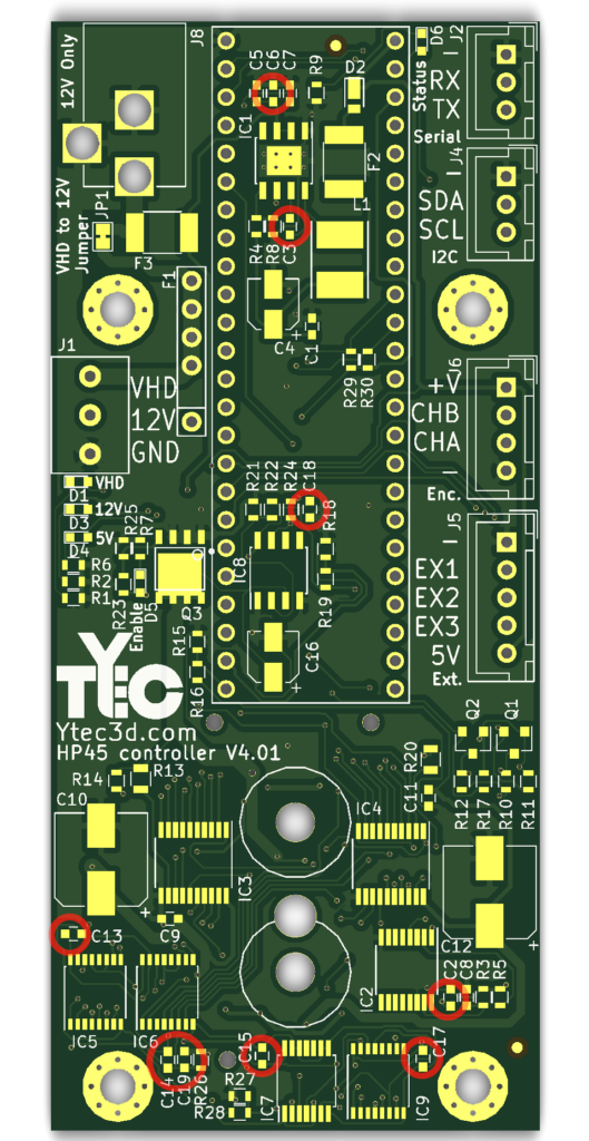
0.1μF Capacitors
There are 9x 0.1μF capacitors. this is 0603 10% 25V. The capacitors have no polarity.
The references for the 0.1μF capacitor are:
- C2
- C3
- C6
- C13
- C14
- C15
- C17
- C18
- C19

1μF Capacitors
There are 5x 1μF capacitors. this is 0603 10% 25V. The capacitors have no polarity.
The references for the 1μF capacitor are:
- C1
- C5
- C7
- C9
- C11
Diodes and Leds
Schottky Diode
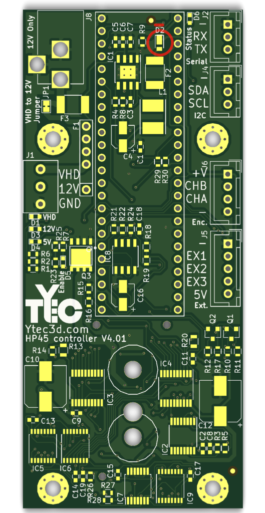
There is 1x schottky diode. this is SOD-323HA. Forward current needs to be at least 1A. Forward voltage should be 500mV at most. The diode has a polarity. The white painted part is the cathode (-).
The reference for the diode is:
- D2
Leds
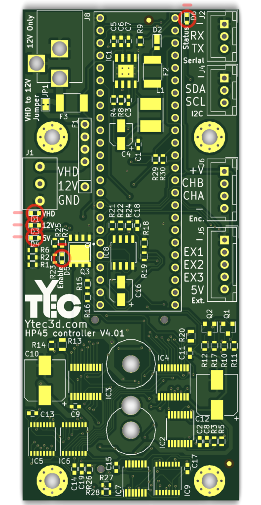
There are 5x Leds. This has a 0603 package. You can use any color. Leds have a polarity. Look in the datasheet of the Led to find the polarity.
The references for the leds are:
- D1
- D3
- D4
- D5
- D6
Inductor
Inductor
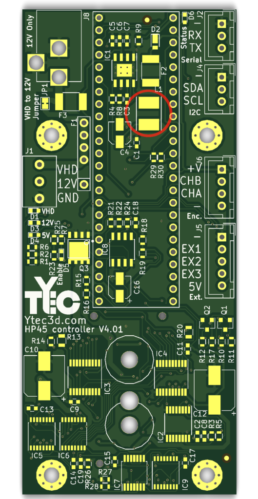
There is 1x inductor. This has a 5040 package. Inductance needs to be 22μH and at least 1A. The inductor has no polarity.
The reference for the inductor is:
- L1
Mosfets
Level shift Mosfet
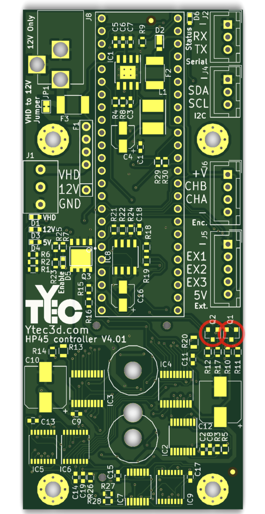
There are 2x mosfets. The package is SOT-23. The type is N-channel. The gate threshold voltage should be lower than 1V. The mosfets should fit only one way.
The reference for the the mosfets are:
- Q1
- Q2

Power Mosfet
There is 1x mosfet. The package is SO-8 PowerPAK. Pin 1 is marked by the round mark in the corner or a marked line. Used type is 78-SIRA12DP-T1-GE3
The reference for the mosfet is:
- Q3
ICs
Power regulator
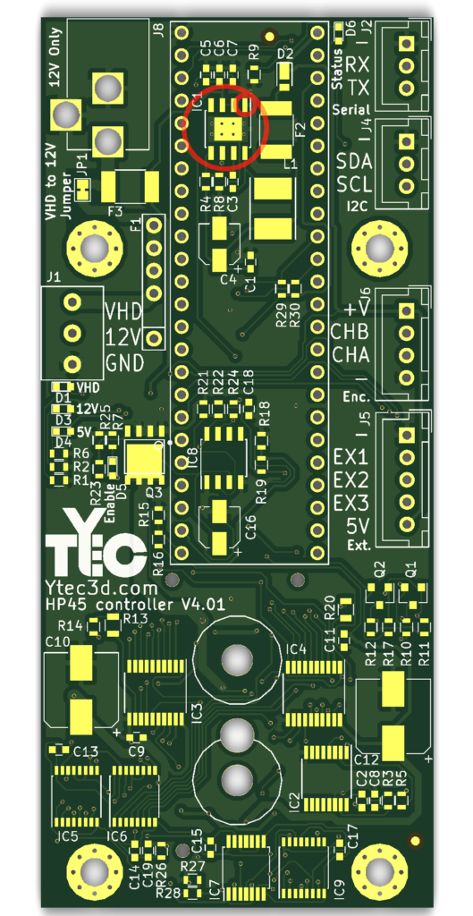
There is 1x LMR36510 power regulator. The package is SO-PowerPAD-8. Pin 1 is marked by the round mark in the corner or a marked line.
The reference for the IC is:
- IC1
Monostable multi-vibrator
There is 1x 74HC123. The package is TSSOP-16 4.4x5mm. Pin 1 is marked by the round mark in the corner or a marked line.
The reference for the IC is:
- IC2
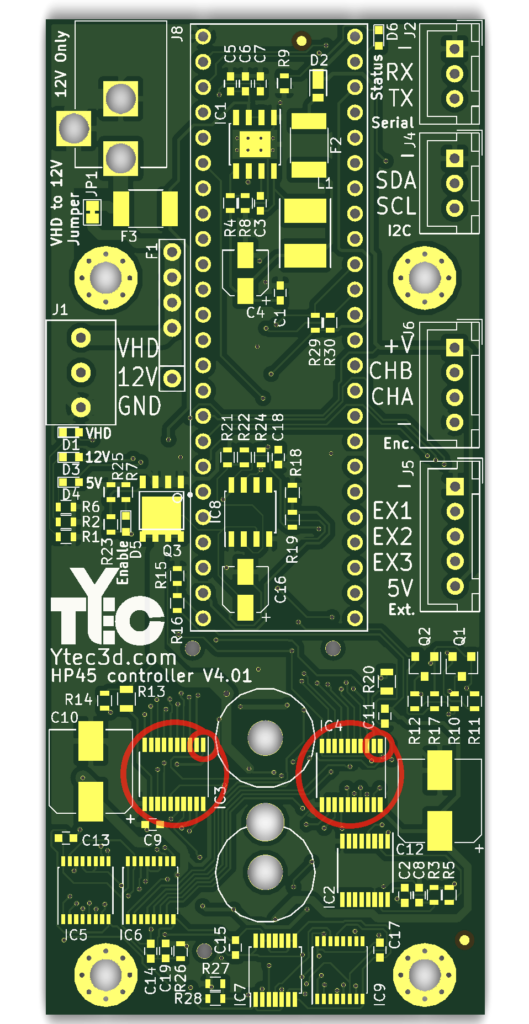
Primitive driver
There are 2x TLC59213. The package is TSSOP-20 4.4×6.5mm. Pin 1 is marked by the round mark in the corner or a marked line.
The references for the IC are:
- IC3
- IC4
Address counter
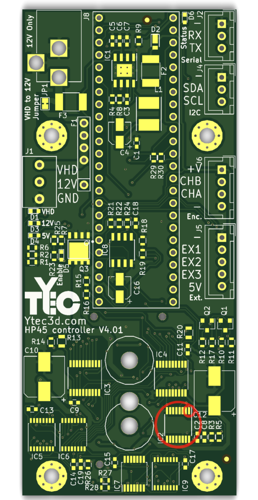
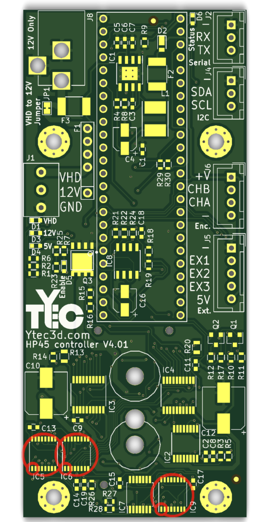
There are 3x HEF4017. The package is SSOP-16 4.4×5.2mm. The chip needs to be 12V minimum. Not all types have the same voltage. The first 3 letters can be different. Pin 1 is marked by the round mark in the corner or a marked line.
The references for the IC are:
- IC5
- IC6
- IC9
AND Gate
There is 1x HCF4081. The package is TSSOP-14 4.4x5mm. The chip needs to be 12V minimum. Not all types have the same voltage. The first 3 letters can be different. Pin 1 is marked by the round mark in the corner or a marked line.
The reference for the IC is:
- IC7
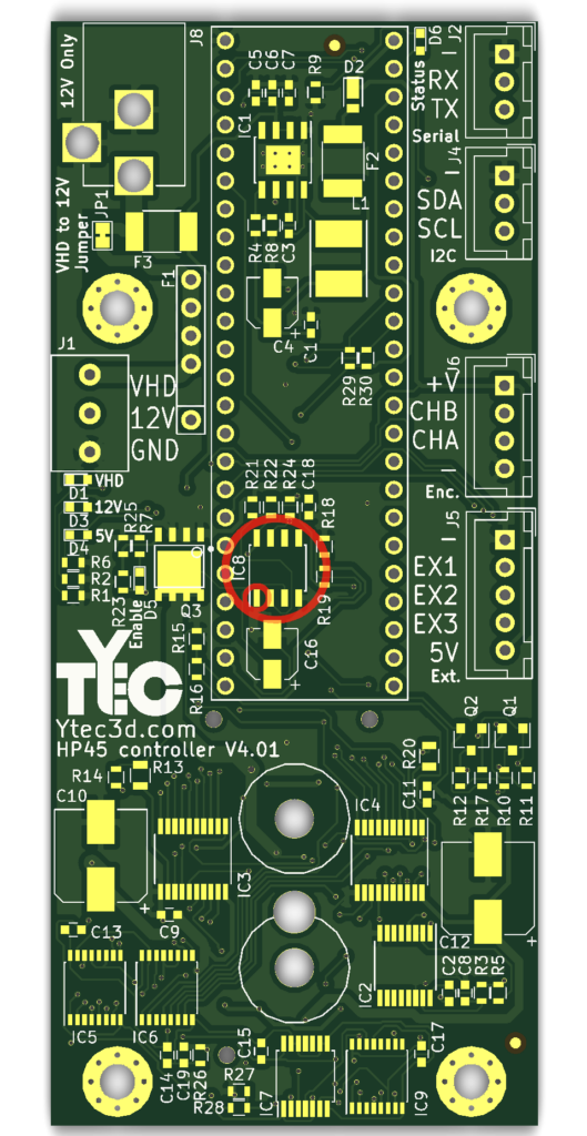
Comparator
There is 1x LM311. The package is SOIC-8 3.9×4.9mm. Pin 1 is marked by the round mark in the corner or a marked line.
The reference for the IC is:
- IC8
Electrolytic capacitors
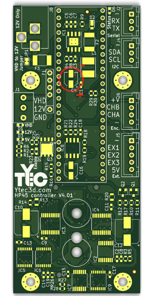
22μF Electrolytic Capacitor
There is 1x 22μF electrolytic capacitor. The capacitance is 22μF. The diameter is 4mm. The minimum voltage is 16V. The capacitor has a polarity. The colored mark is the cathode (-).
The reference for the 22μF capacitor is:
- C4
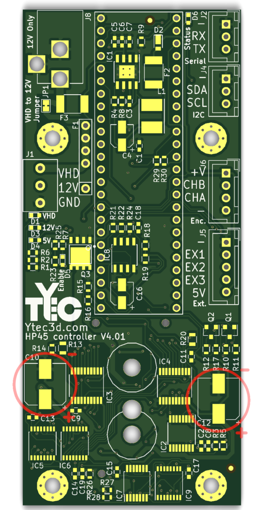
100μF Electrolytic Capacitors
There are 2x 100μF electrolytic capacitors. The capacitance is 100μF. The diameter is 8mm. The minimum voltage is 25V. The colored mark is the cathode (-).
The reference for the 100μF capacitor is:
- C10
- C12
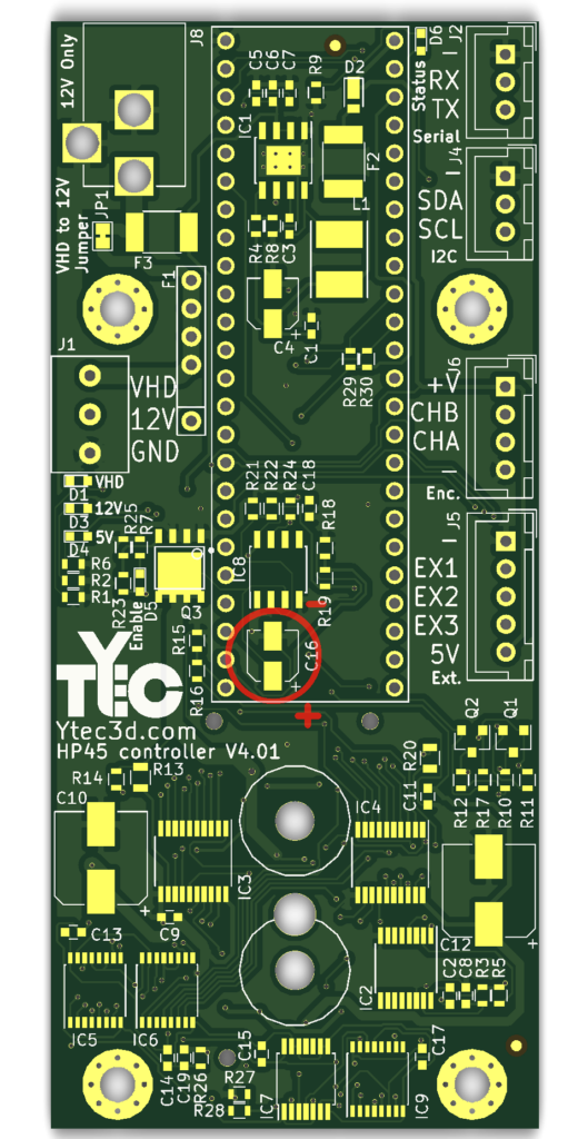
1μF Electrolytic Capacitors
There is 1x 1μF electrolytic capacitor. The capacitance is 1μF. The diameter is 4mm. The minimum voltage is 25V. The colored mark is the cathode (-).
The reference for the 1μF capacitor is:
- C16
Fuses
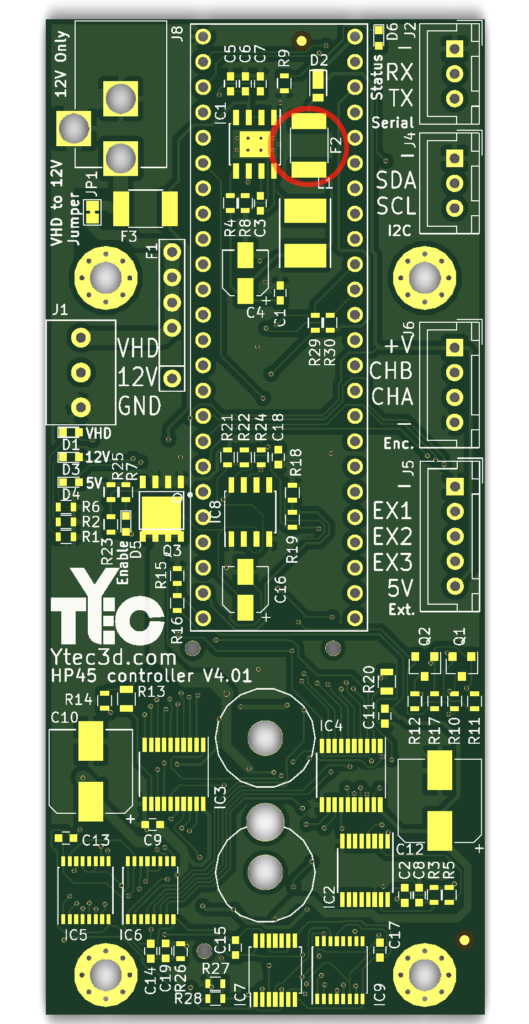
5V Fuse
There is 1x 5V polyfuse fuse. The hold current is 0.5-1A. The maximum voltage needs to be at least 15V. The package is 1812. Fuses have no polarity.
The reference for the 5V fuse is:
- F2
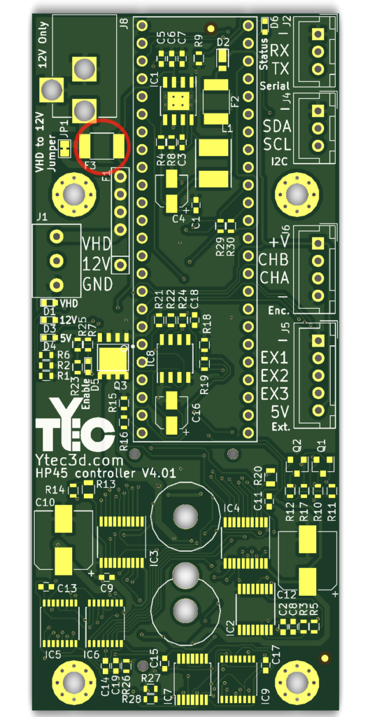
12V Fuse
There is 1x 12V polyfuse fuse. The hold current is 1-1.5A. The maximum voltage needs to be at least 15V. The package is 1812. Fuses have no polarity.
The reference for the 12V fuse is:
- F3
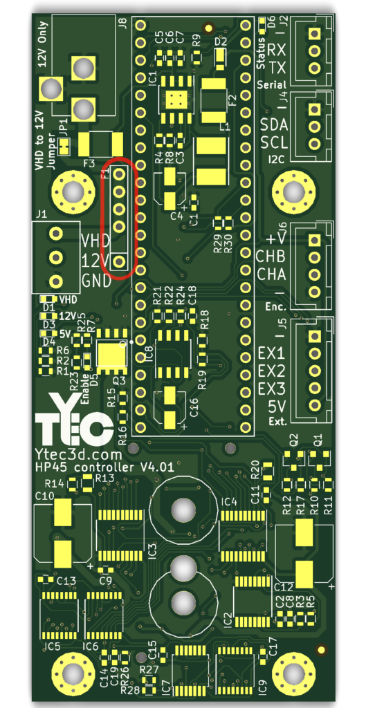
VHD Fuse
There is 1x VHD polyfuse fuse. The hold current is 4A. The maximum voltage needs to be at least 15V. The package is radial through hole. Many pitches will fit. Fuses have no polarity.
The reference for the VHD fuse is:
- F1
Connectors
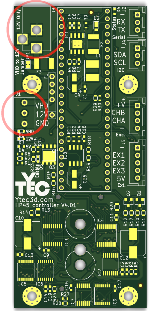
Power connectors
There are 2x power input connectors. 1x DC barrel jack and 1x 3 pin 3.5mm screw terminal. Both need to handle at least 5A of current. The inputs need to face away from the PCB.
The reference for the power connectors are:
- J1
- J8
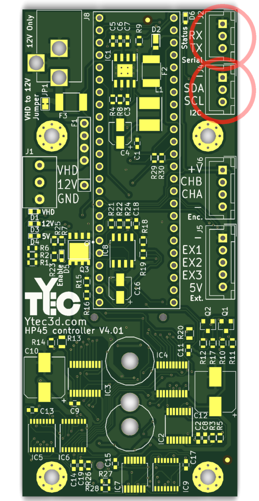
Serial and I2C connectors
There are 2x data connectors. They are of the JST-XH 2.5mm 3 pin straight type. The openings need to match with the silkscreen.
The reference for connectors are:
- J2
- J4
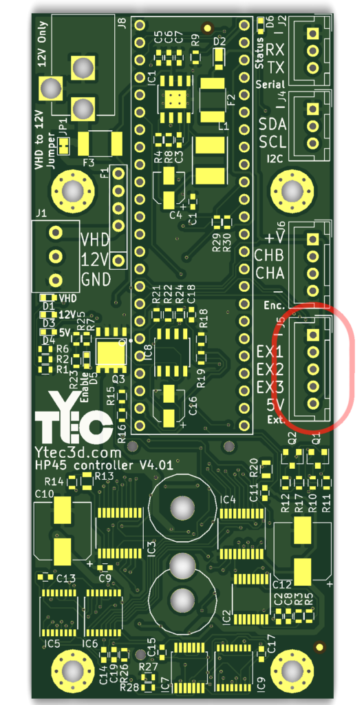
External connectors
There is 1x external connector. This is of the JST-XH 2.5mm 5 pin straight type. The openings need to match with the silkscreen.
The reference for connector is:
- J5
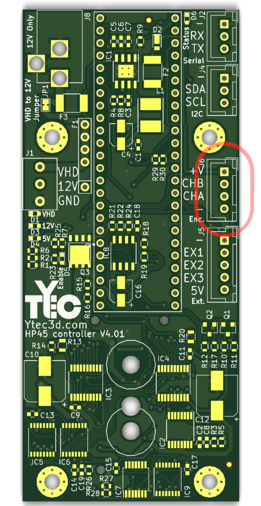
Encoder connector
There is 1x encoder connector. This is of the JST-XH 2.5mm 4 pin straight type. The openings need to match with the silkscreen.
The reference for connector is:
- J6
Micro-controller
Teensy 3.5
There is 1x Teensy 3.5. This is a development board with a ARM Cortex-M4. To mount the Teensy you will need 2x 24 pin 2.5mm female header. Optionally you might need matching male headers.
The microcontroller has no reference on the board, only 2 headers.
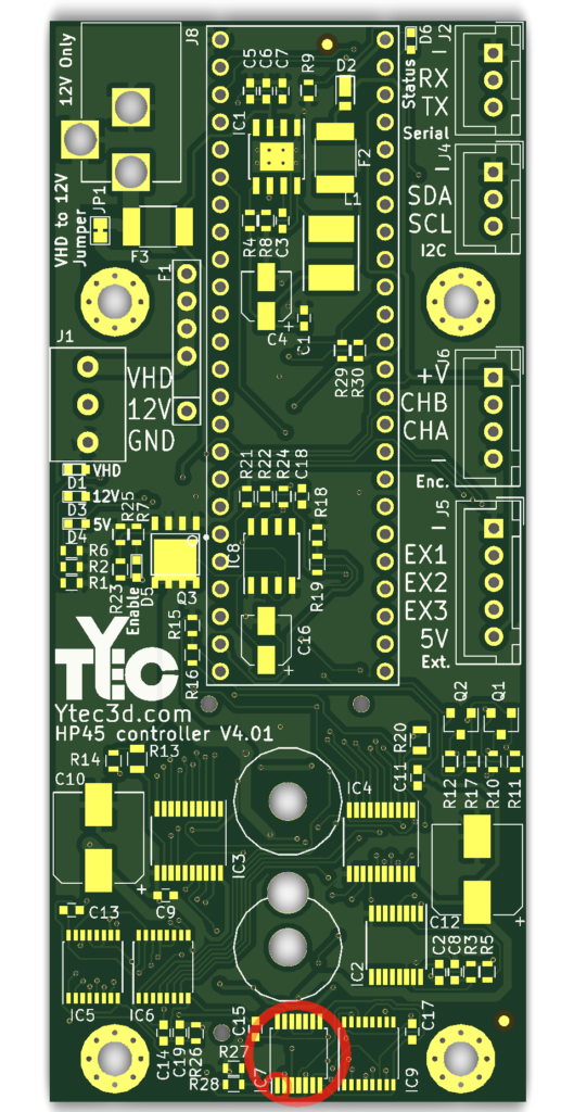
HP45 connector
There is 1x HP45 connector. This is a plastic housing with 52 springs and pins, and 2 screws and washers to mount them.
3 holes align with pins in the HP45 connector. 2 screws and washers are then used to mount the connector. Be careful not to drop the connector. The pins and springs can fall from the housing.
The HP45 connector has no reference on the board
Assembly
The controller can be assembled in many ways. It is presumed that there is prior SMD experience before assembling this controller. Especially the ICs have fine pitches (TSSOP at 0.65mm) and under package pads which require hot air soldering.
The easiest soldering order is the one given on the page, going from small to large SMD components. In case the board is reflowed, all the SMD components need to be placed first, then the components need to be reflowed. After that the through hole components can be soldered. When soldering by hand the exact order is slightly less critical.
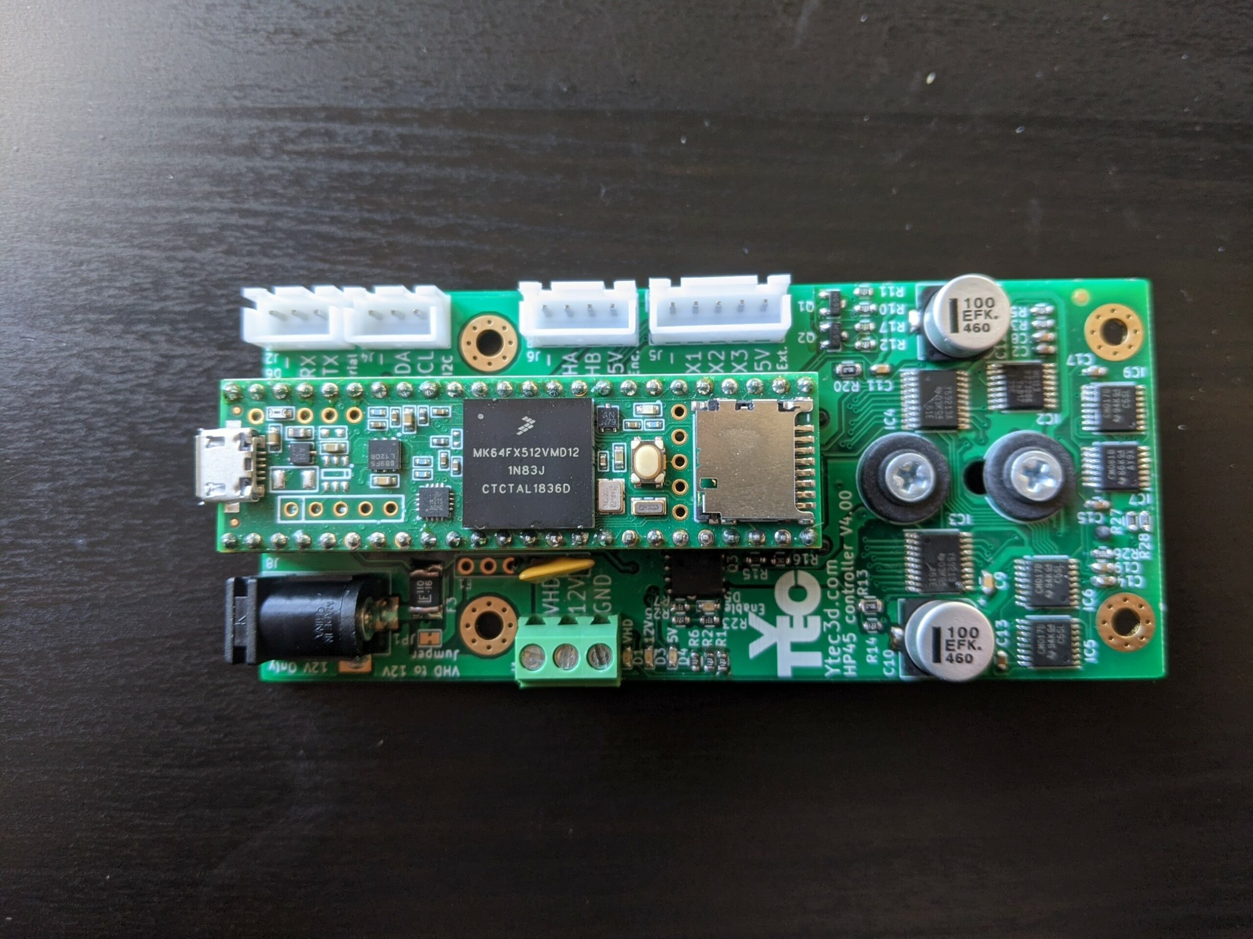
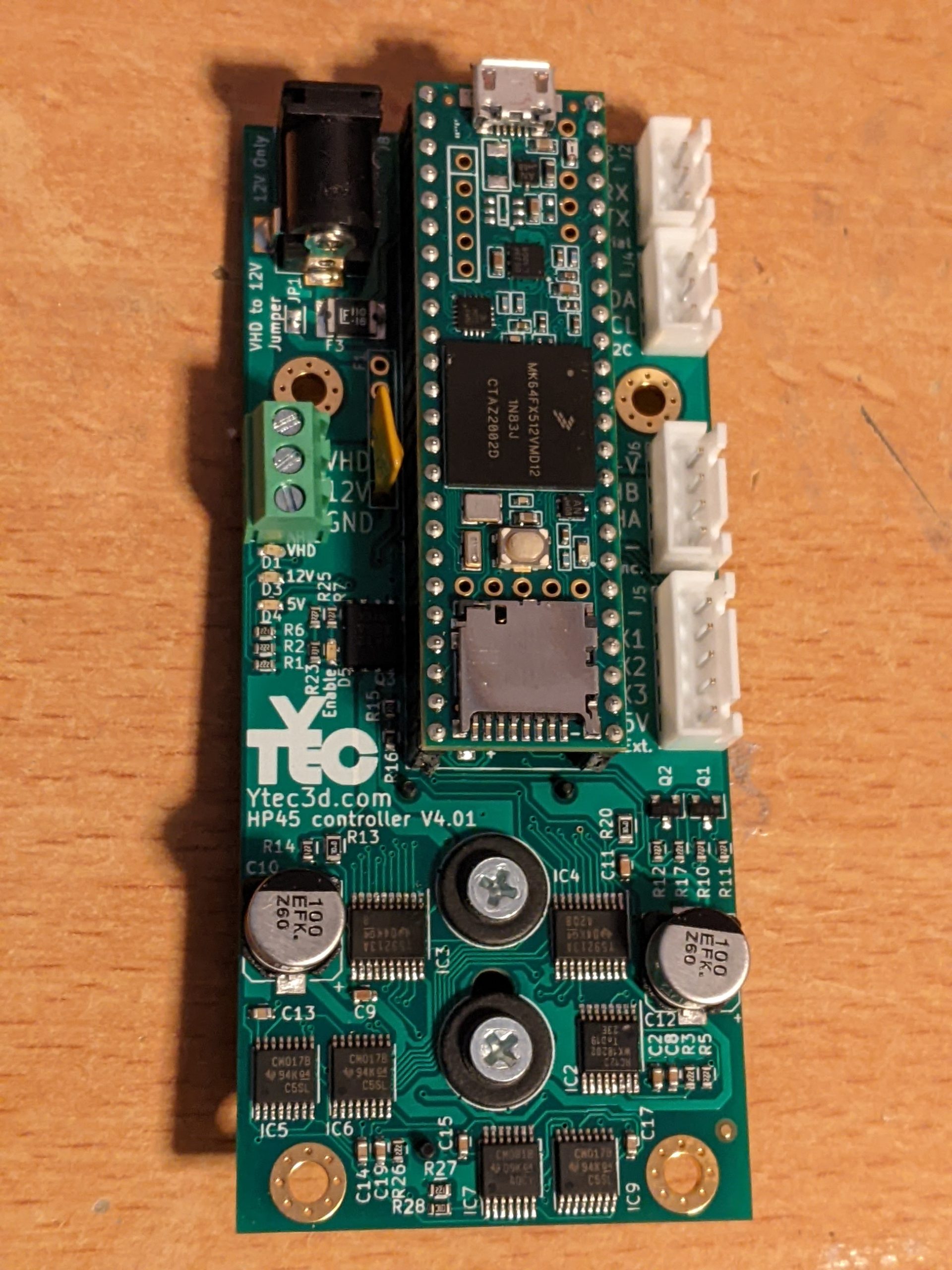
Assembled board
When you are done the board should look like the images below.


Placing the microcontroller
The Teensy 3.5 is mounted in the 2 24 pin headers towards the top of the board. The USB points in the same direction as the DC jack, and the SD card points towards the HP45 connector. Be sure the microcontroller is in the correct place. ALL header pins need to be in the headers. If the microcontroller is one pin over in either direction, you risk destroying the microcontroller.
Testing the controller
Before plugging the controller in, there should be a visual inspection to verify there are no shorts. The first time the controller should be powered by a current limited power supply at 100mA/12V with no microcontroller. If there are any shorts the power supply should limit the current. All 3 power leds should light bright. Now the controller can be inserted and the controller can be powered again with the current limited supply. Only after there are no shorts detected, can the board be powered with 4A 12V.
After flashing the firmware, the controller can test itself. This can be done through the software with the button “Test”. No new warnings should pop up.