Table of content:
- Part 1: The beginning
- Part 2: Electric overhaul
- Part 3: PC power
- Part 4: Trying to print
- Part 5: INK!
- Part 6: (you are already here)
- Part 7: Making printheads
- Part 8: Printing in powder
The Z400 printbed size
Before I start. I still needed to measure the print size of the Z400. It is not in the manual, and I have no other place to share yet. It is exactly US letter size (about 280mm by 215mm) and about 350mm in height. A fairly sizable printer, and about enough for my ultimate goal with a powder printer.
(Edit: The vertical stroke of each piston is around 350mm, but the usable build size for the printer is only 8″ (200mm). They probably made the stroke of the pistons equal, but since the build piston is bigger than the feed piston, the feed piston needs more stroke than build piston.)
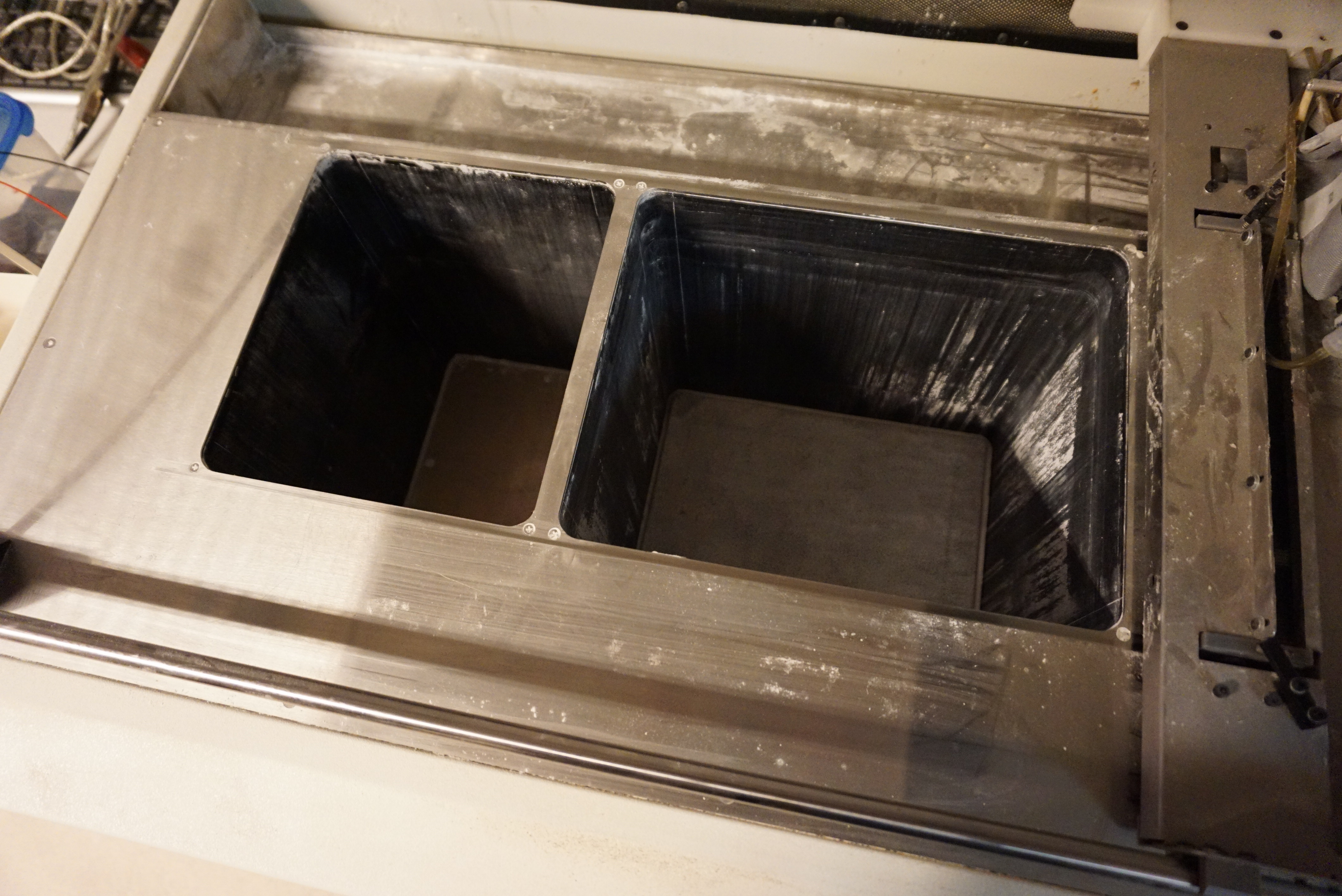
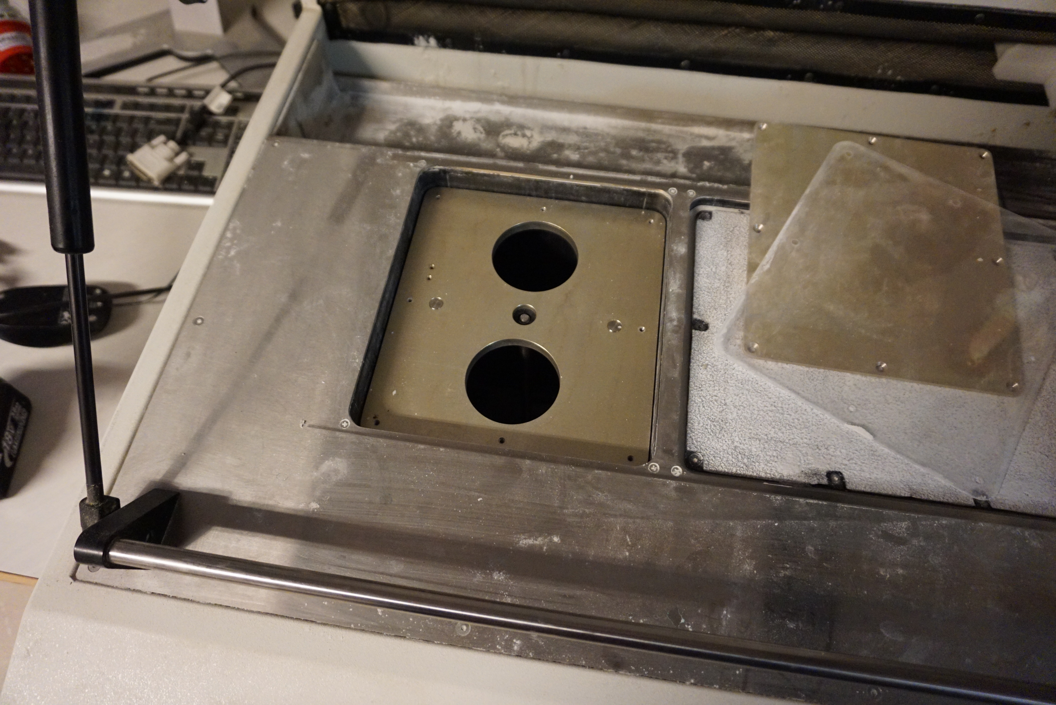
The problem with the pistons
The pistons hold the powder I will print with. Currently, these pistons wobble and have a 1-2mm gap in the edge. The seals not only prevent the powder from going past the piston, they also are 50% of the guidance of the piston. The bottom bearings do not block rotation. Obviously, printing right now would give a big mess. The piston seals needs to be fixed.
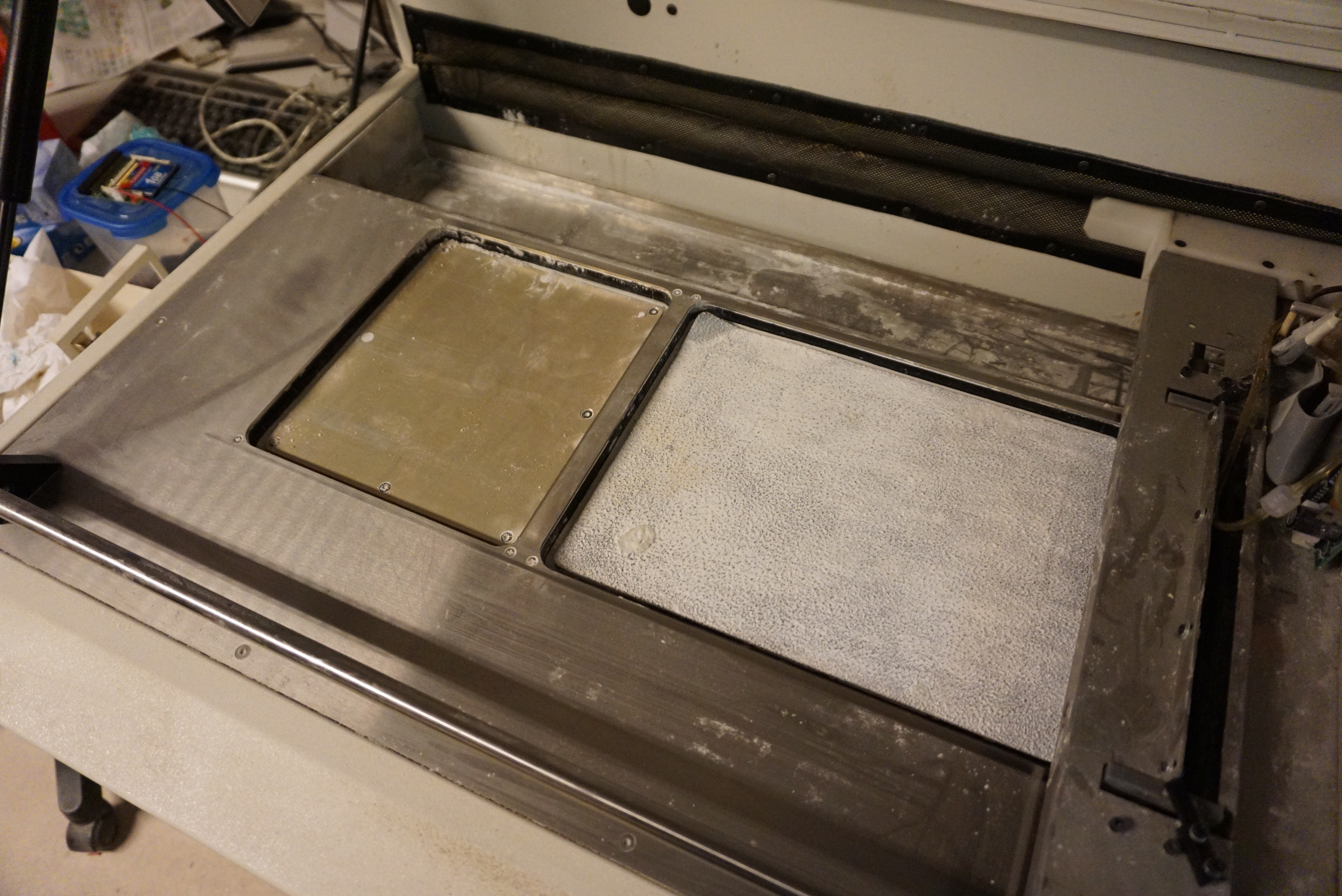
Taking them apart
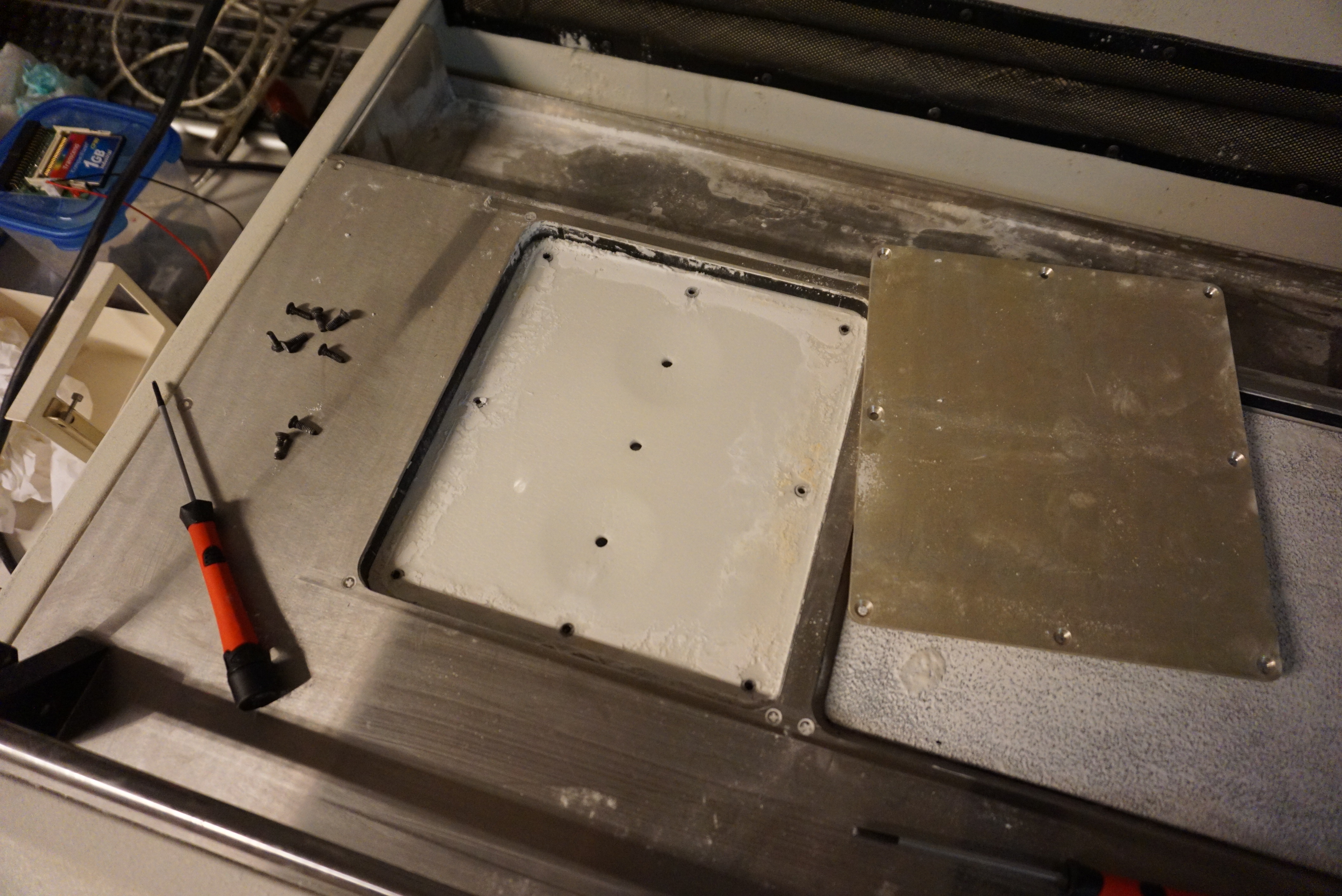
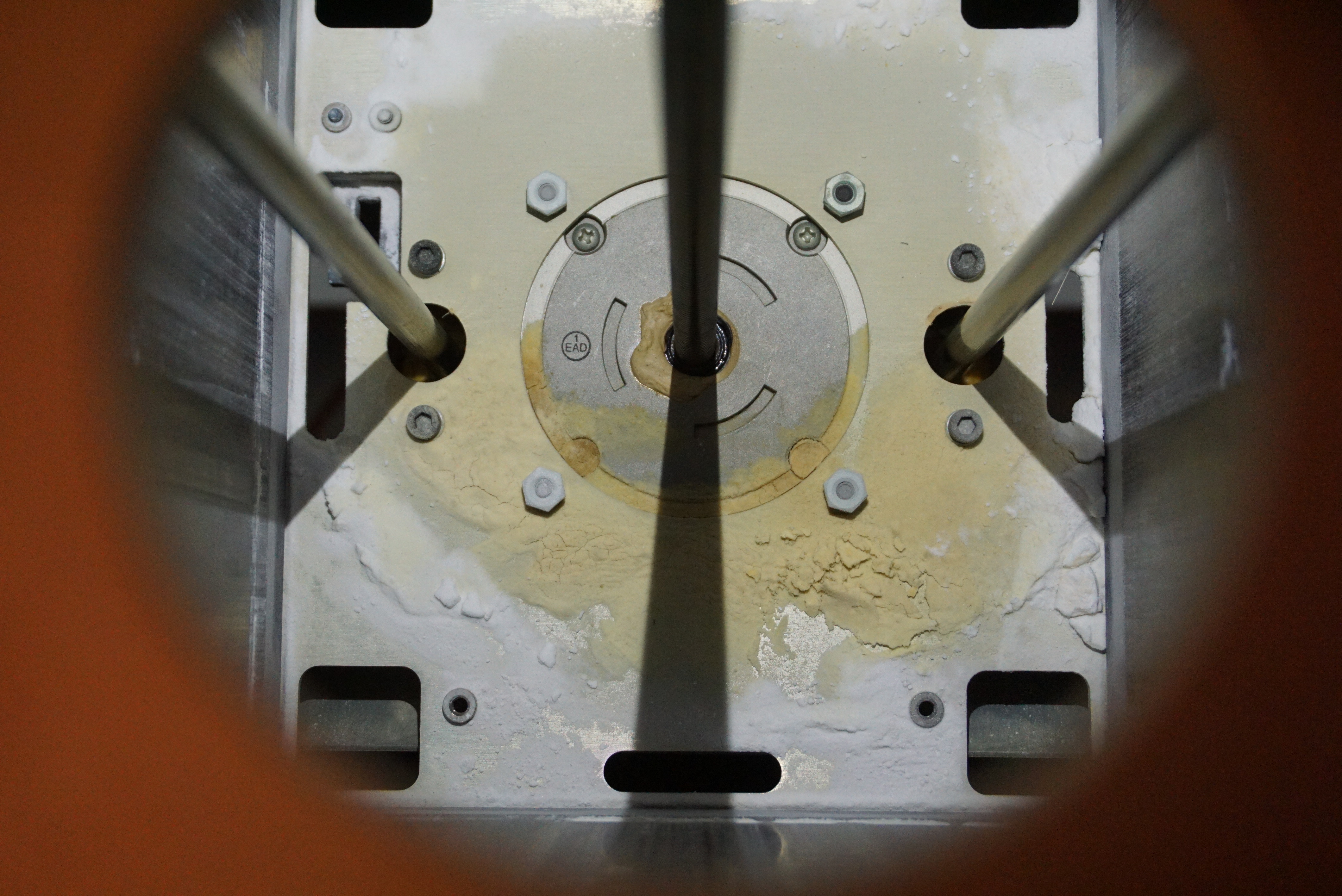
The left piston is the feed piston and the right piston is the build piston. The feed piston is pretty straight forward, with 8 screws in plain sight. The build piston has a rough rubber mat glued in place. I know from my own experience that thin layers of powder (<5mm) have a tendency to slide when a new layer is deposited, so I suspect that the mat prevents the layer from sliding. It is also very much in the way of the 10 screws holding the build piston together. I have opted to cut the rubber away where the screws are. This should not interfere with the function, and leave the screws free for when I need to do more maintenance.

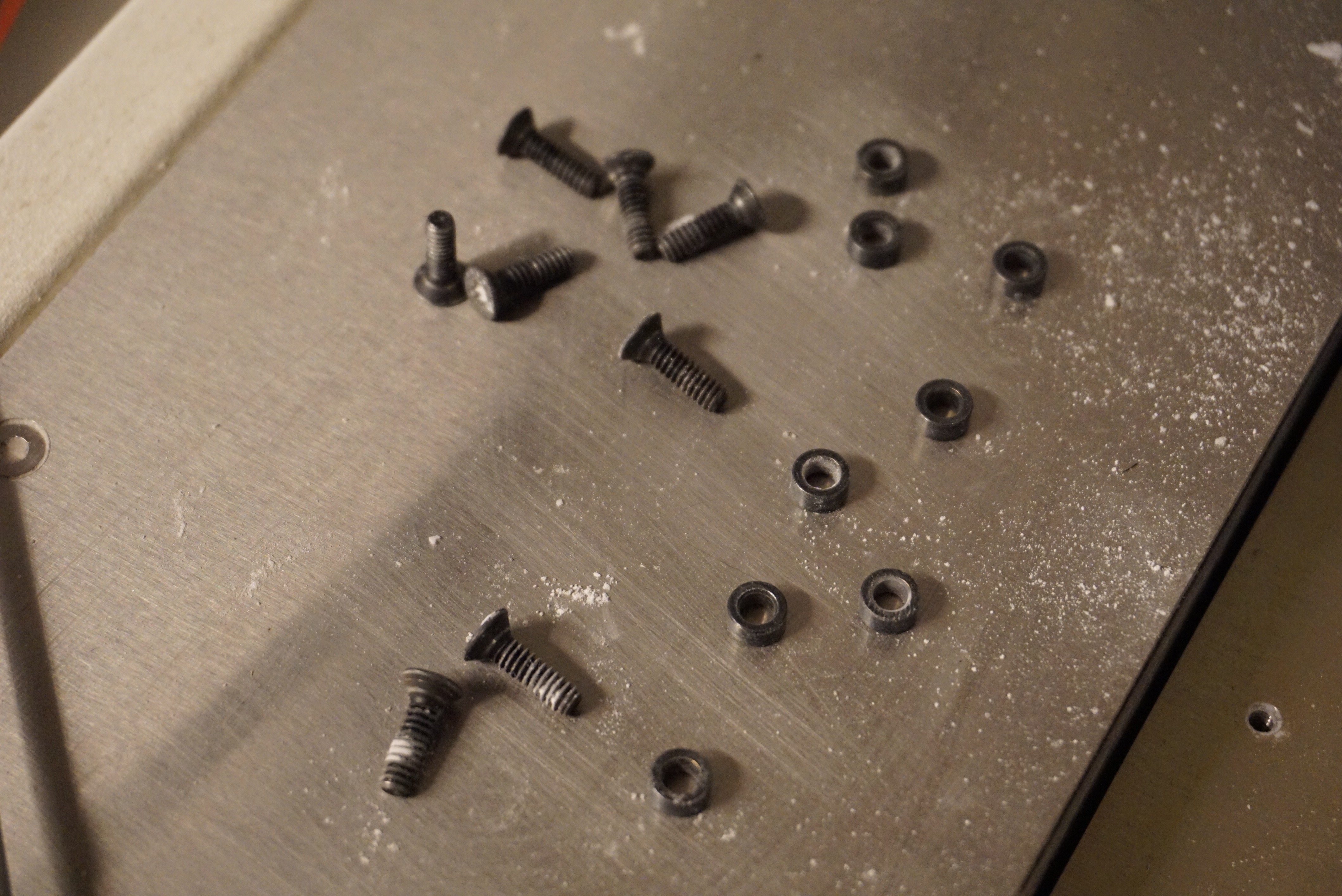
The piston is a sandwich of 4 layers. At the base is an aluminium frame that holds the guide rods and the lead screw. Then there is a soft seal, made of some sort of foam about 3mm thick (1/8″). Then a thin layer of plastic (0.1mm thick) presumably to keep the powder out of the seal. Last, there is an aluminium top plate. There are rings between the top and bottom plate to prevent the screws from compacting the seal too much.
Getting to the seals

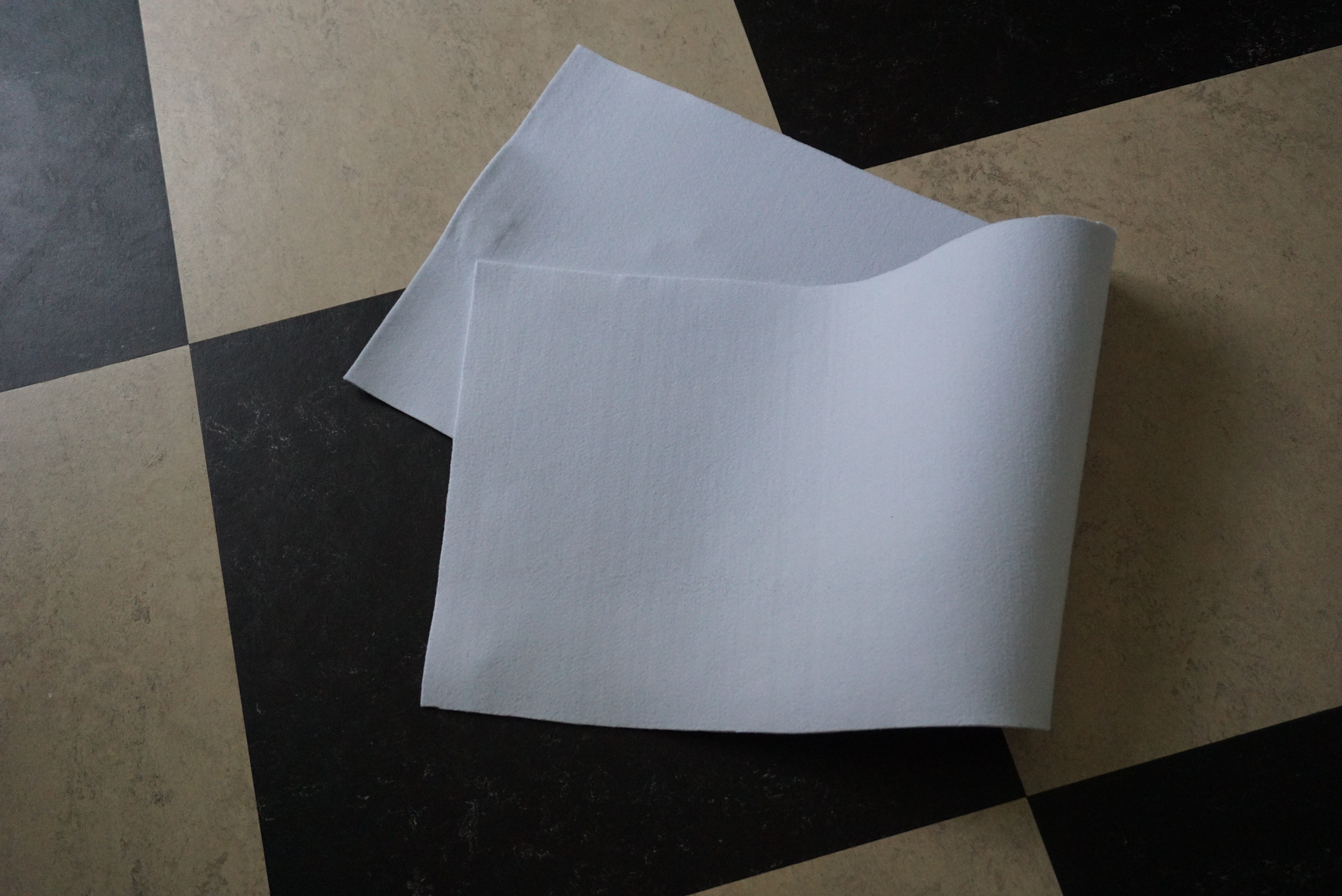
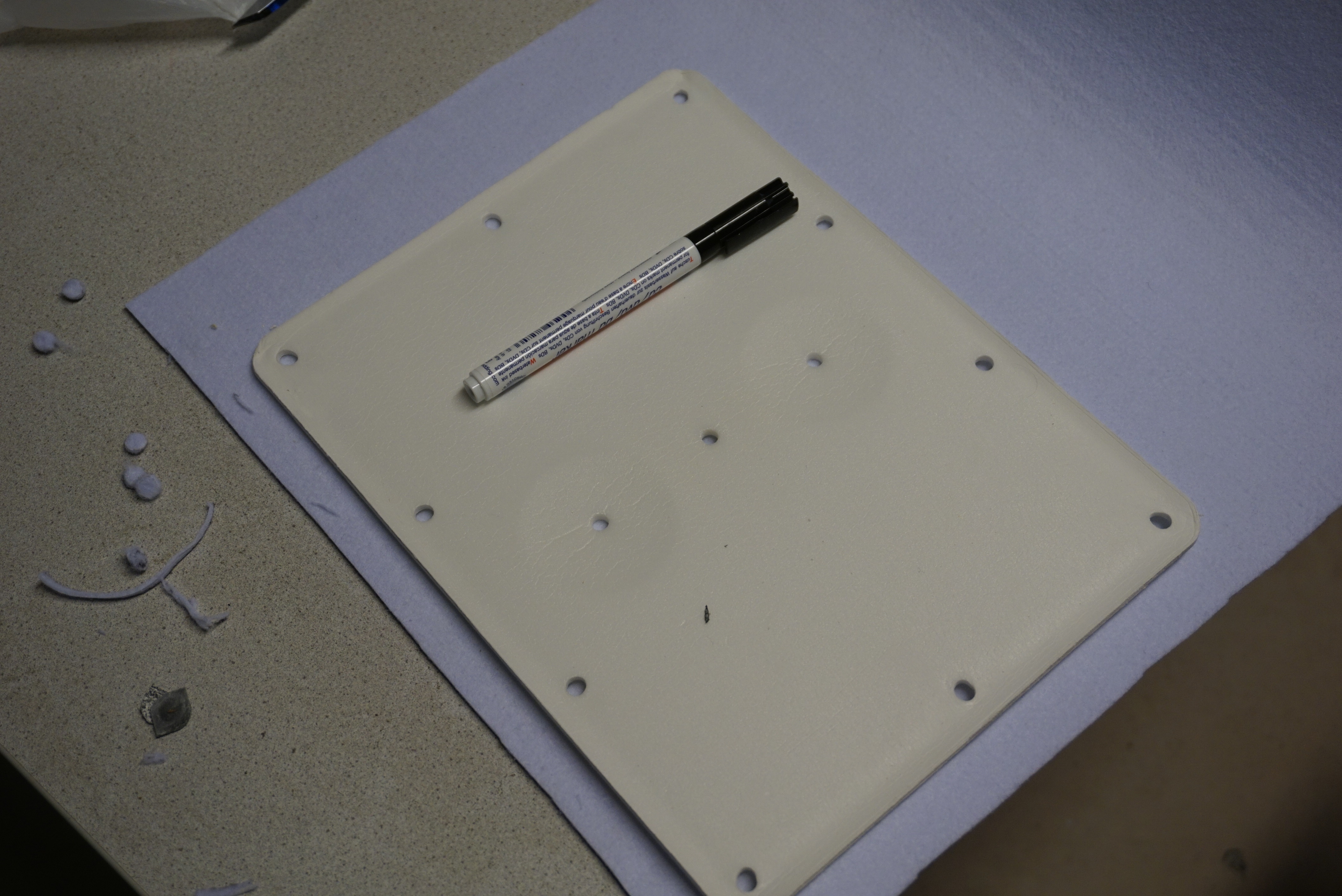
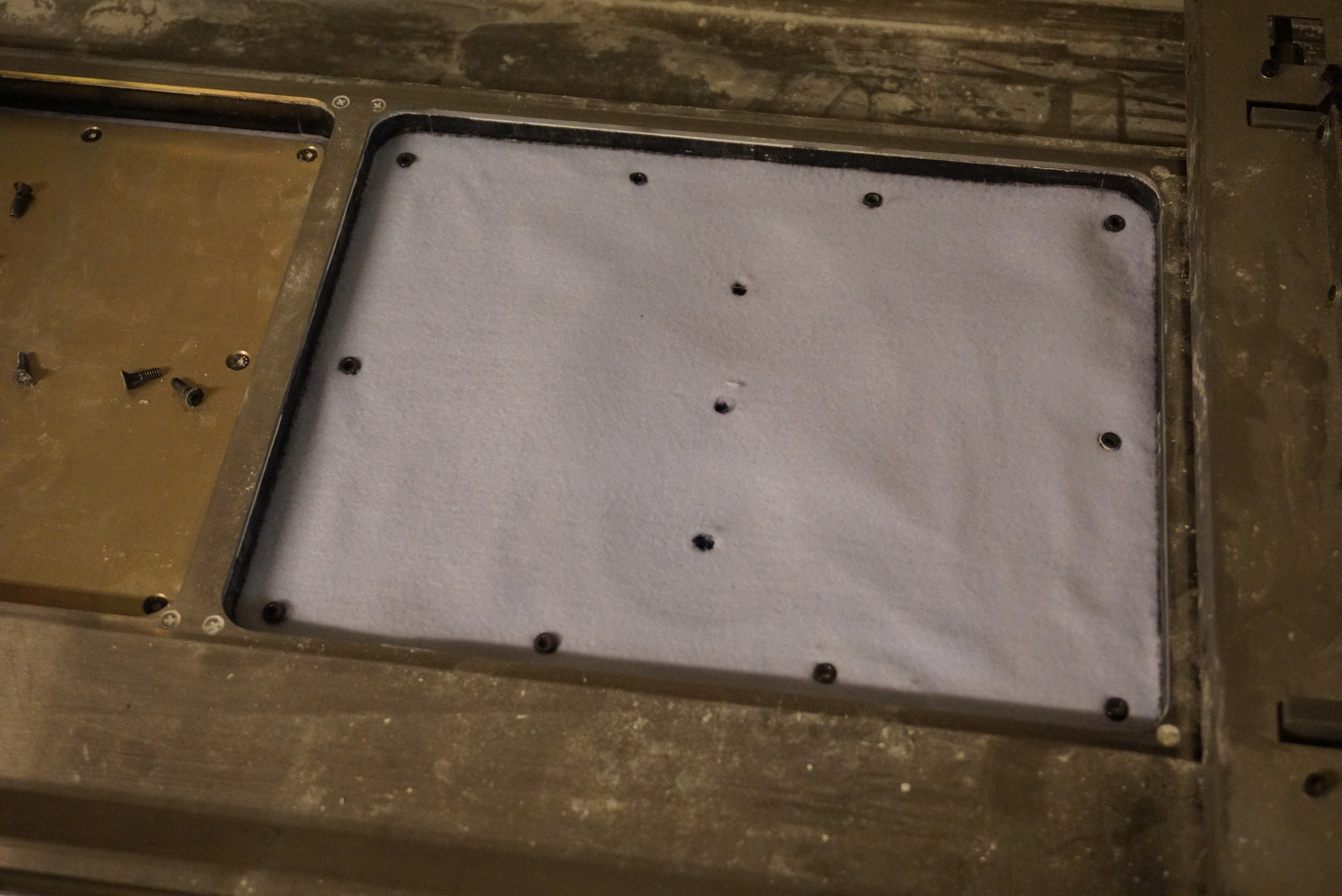
Making new seals
Getting the exact foam is going to be difficult. I opted to use 3mm thick felt. Felt is tough, low friction, and easy to get. The old seals were laid on top of the felt, and the contours and holes were marked with a marker. The outside contour was cut slightly oversized with a pair of scissors. The holes were punched out with an 8mm thick tube and a hammer.


Reassembling
The new seals were put in place, the rings were placed in the holes, the old plastic was put on top of that, and the top plate was installed. I was worried that I made the felt seal too oversized, but I am happy to report it feels all right. No wobble in the piston, and no visible gap. The piston also still moves up and down, which I really appreciate.
I also took this moment to grease the piston rods and lead screw, but again, no photos of me greasing these parts.
Almost there
In the next part I will prepare a printhead so I can finally make a 3D print on the Z400. We are getting really close now.